Faced with the now-common !CHANGE BATTERY! message on its display, I recently had to replace the battery in an RY30 drum machine I’d bought.
Having read a few posts on the subject, I decided I was reasonably confident of being able to do the swap, the hardest part of which involves de-soldering and soldering-in a new CR2032 coin-type battery — the type with tabs already fitted (you can’t just remove the existing battery as it’s not in a separate holder).
If you have even the most basic of soldering experience, this should be very straightforward… but do it at your own risk.
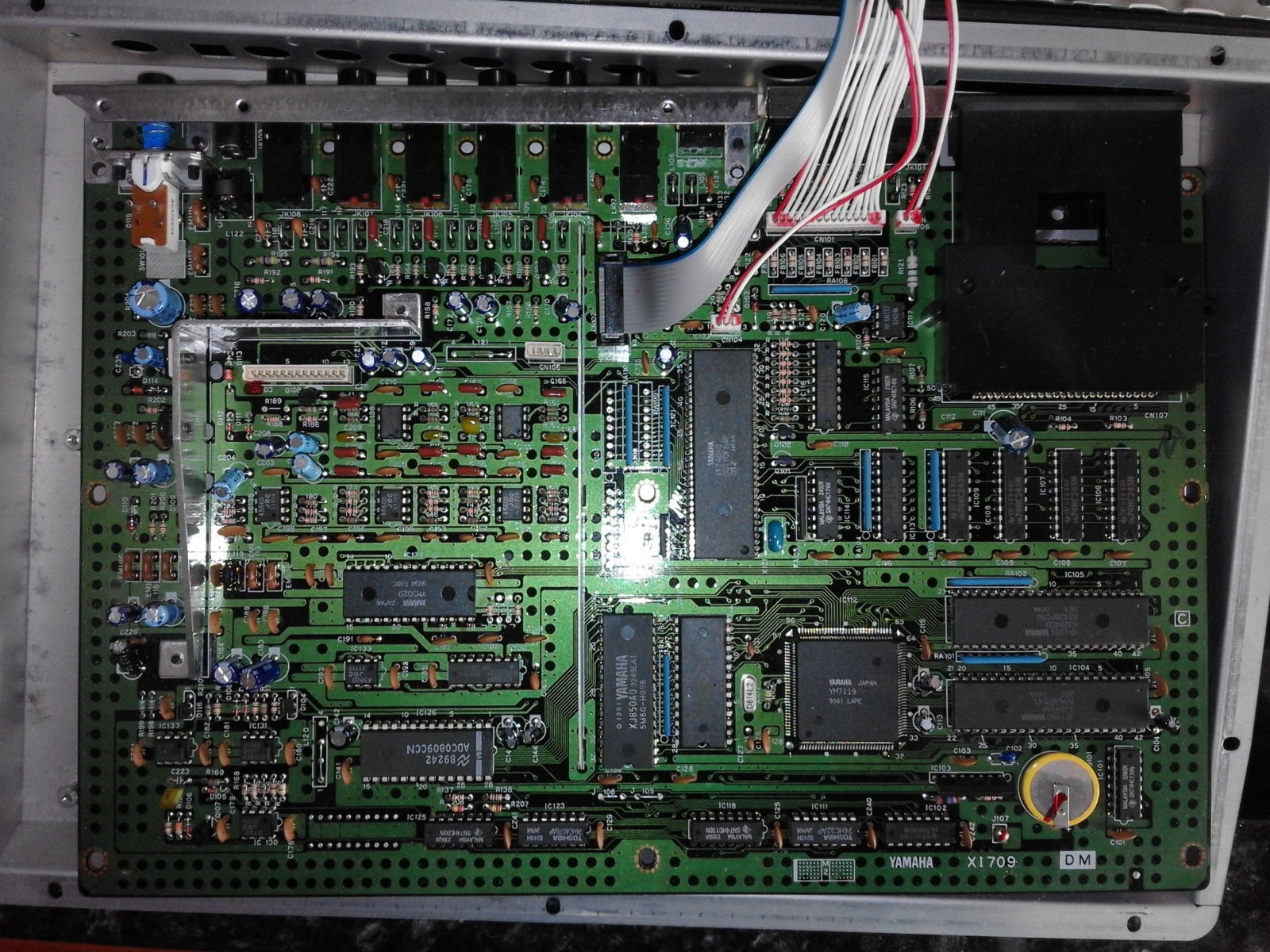
I have very little experience of soldering, and couldn’t find any decent pictures of the mainboard online, so I opened up the machine via a set of simple cross-head screws around the edge and rear, easily removed with a normal Phillips-type screwdriver, in order to take a look:

After removing all of the external screws, I carefully lifted off the top half of the case:
Note that the upper board is still attached by two cables, so you can’t move it far.
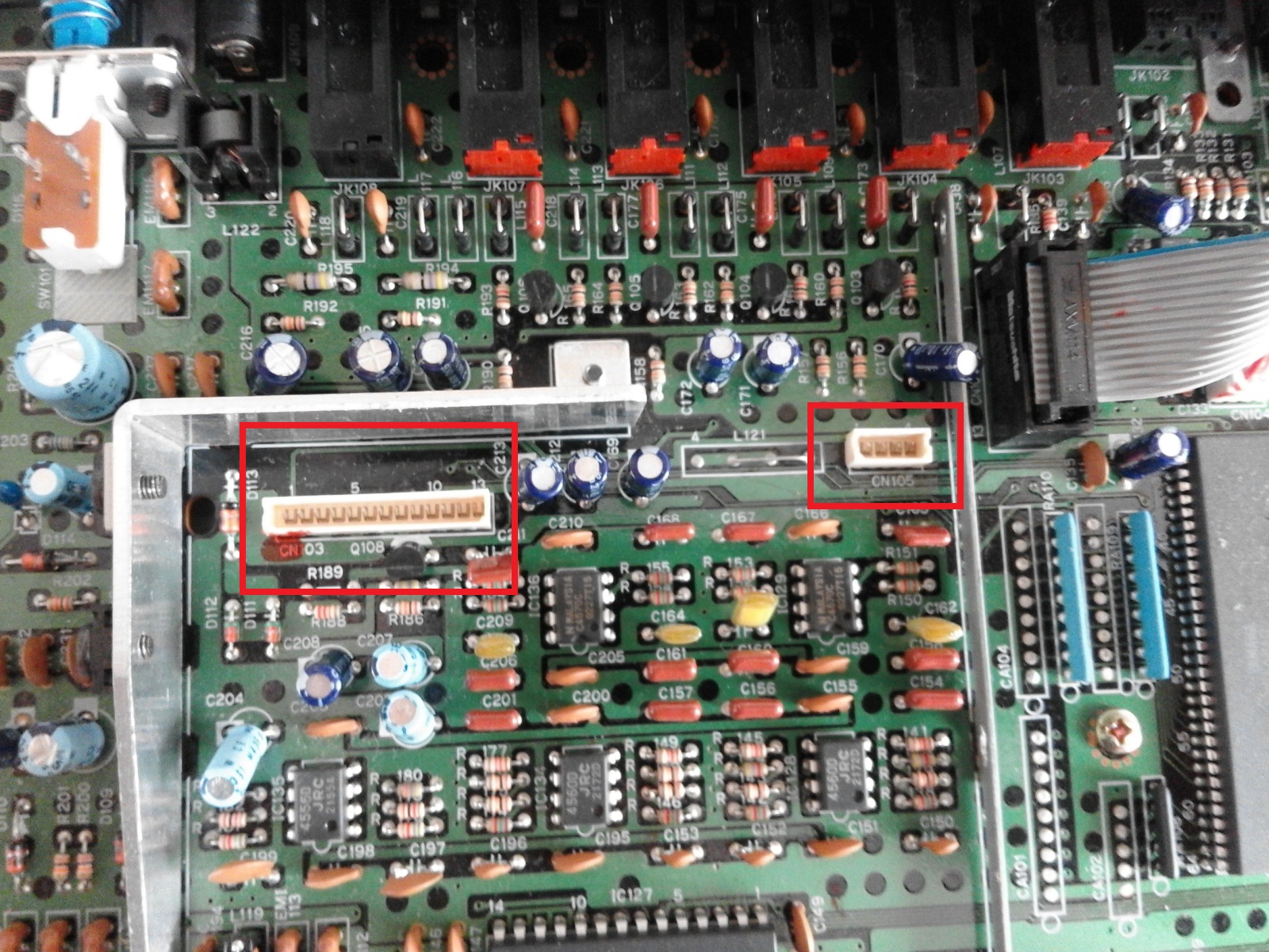
The cables’ sockets, with cables removed, are highlighted here:

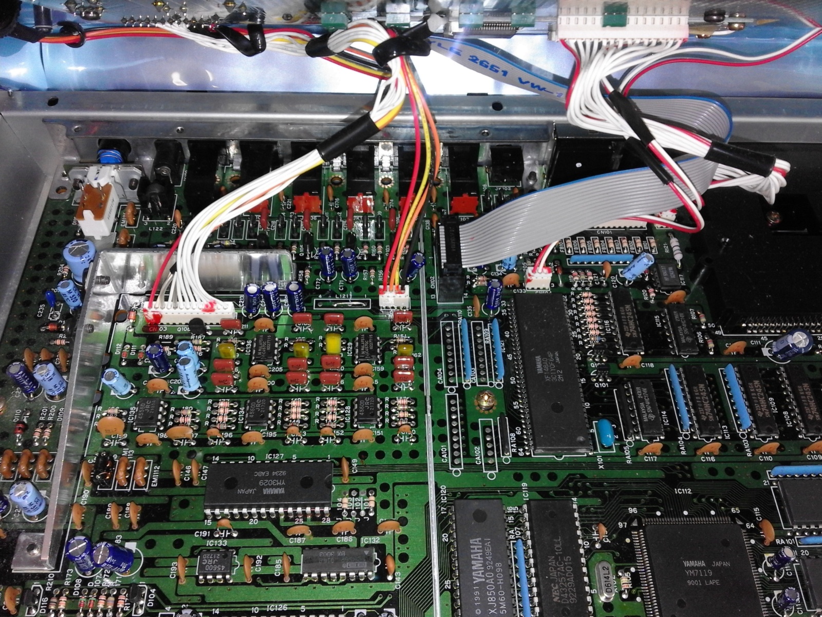
Unplug the two cables from the mainboard and remove the top half.
I only have enough knowledge to be dangerous, so I was very wary of touching the capacitors, making it a little fiddly in terms of access, and the larger plug is made of a very flexible plastic, so it bends readily.
However, with a combination of flat screwdriver edges and swearing, both cables came free without too much trouble.
Here’s the underside of the upper board, showing the other end of the two cables. Note the underside of the jogwheel on the left, just out of interest.

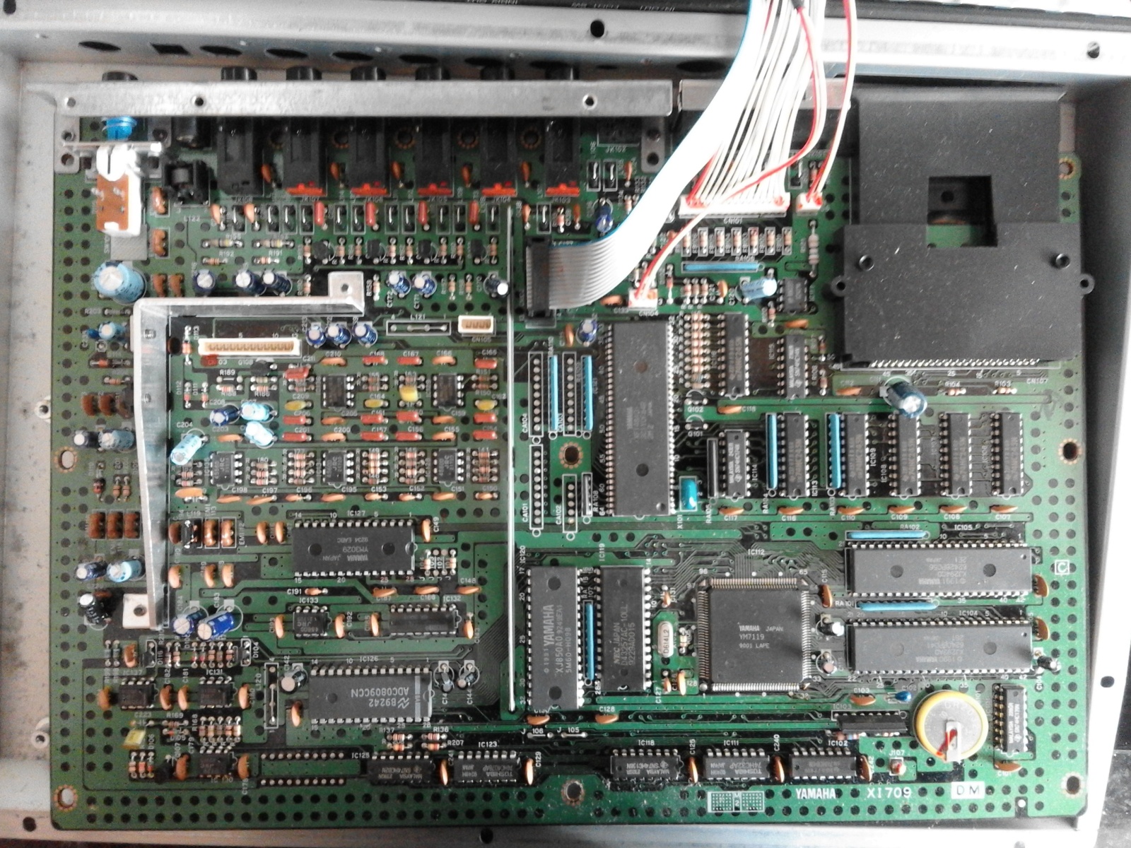
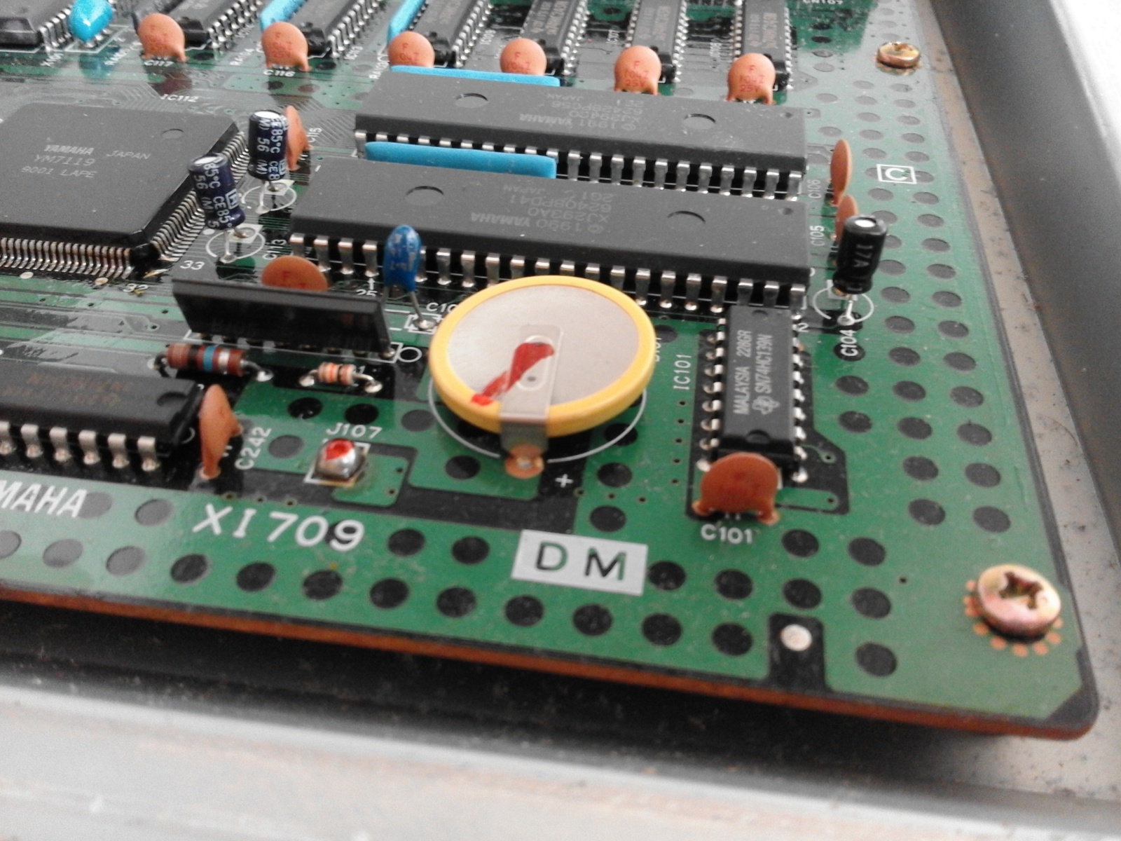
With the rear of the unit facing away from you, the battery is located at the lower-right of the board (that round yellow thing!), and is secured by means of two legs soldered into the board.
Remove the seven brass screws holding the mainboard to the base of the unit:
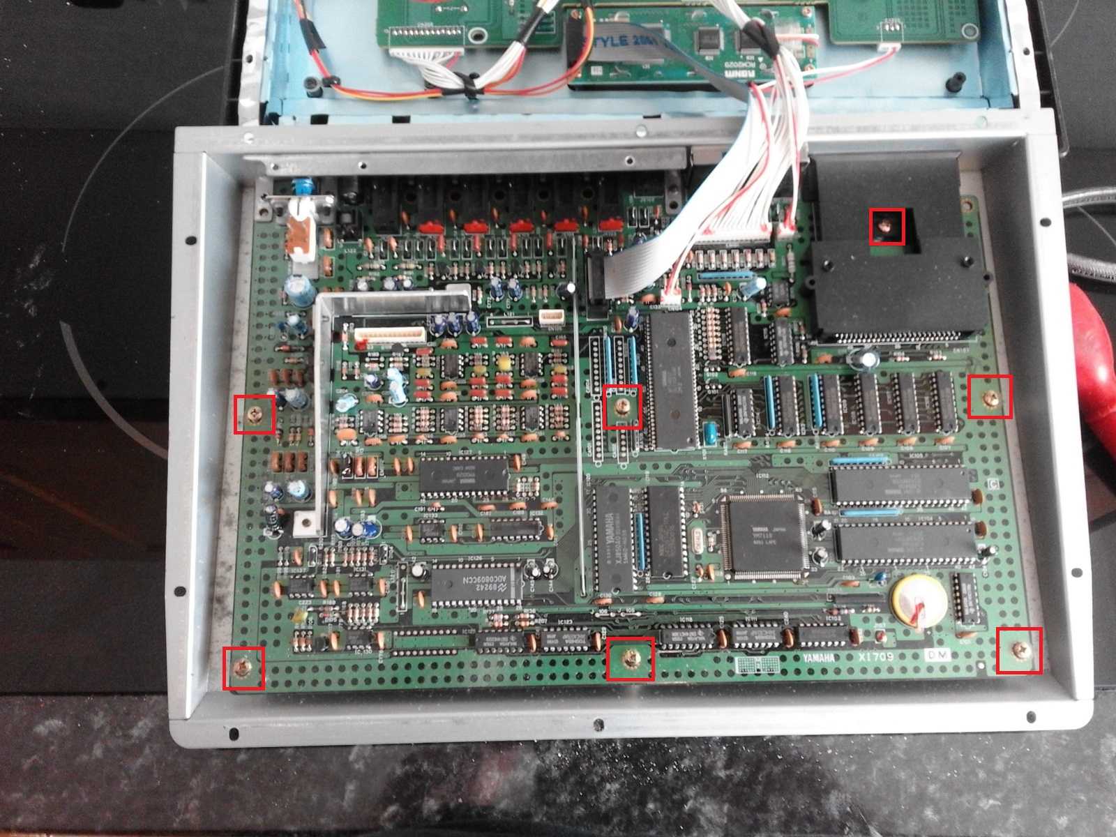
Be careful with the one at the top right, inside the black data-card shield — try not to drop the screw inside!
Carefully slide the board towards you and it should come free — note that it is still attached by further cables, but this gives just enough access to replace the battery.
There’s nothing to stop you removing the remaining cables if you want better access, but do take some photos first!
I would suggest doing as I did, and giving the board and lower base a sweep with a soft camera brush if you have one, just to remove any dust that has accumulated over the past three decades!
With a soldering iron heated up to full operating temperature, I touched the base of each leg on the underside of the circuit board to melt the solder and they easily came free.
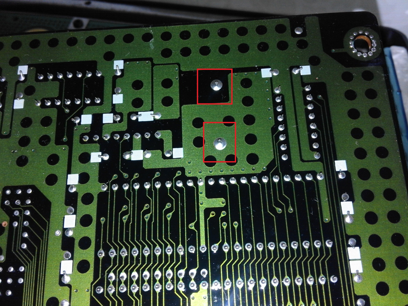
You can see the two large solder pads underneath the mainboard here, with plenty of space around them for the clumsy:
Here’s the board with battery removed:

My photos run out here, as I had to wait days for the battery to arrive, but refitting them was a case of adjusting the legs of the new battery holder so that they were reasonably ready for the pads, applying heat from the top and bottom of each hole.
With the first leg in approximately the right place, heating the underside of the pad for a few seconds allowed the leg to fall through easily; the same for the other leg. (Note that you should avoid heating the board for too long, and that the heat will spread along the circuit traces, so other areas can become very hot!)
Make sure you have the battery the right way round!
When I went to apply solder to the pads underneath, I found that the existing solder had already secured the battery in place and so frankly didn’t bother!
You may need to apply some solder to each underside pad, heating up the solder pad/leg and then simply touching the solder wire to it to get a small amount in place. Do one at a time, letting the first leg cool a little before continuing.
I re-fitted the two cables I unplugged earlier (they only fit one way — there is a slight indent on each so they should go in easily if inserted the right way round).
I connected the power supply up at this point and tested the display, also performing a factory reset: to do this, hold Dec, Pattern and PERC2 (L), then hit Stop/Continue at the prompt. This will clear all patterns and user data, leaving only the original manufacturer data in place.
The !CHANGE BATTERY! message should no longer appear, but any such problems may mean starting over, removing the two cables and perhaps turning the battery around, but it all went very smoothly for me.
Assuming no errors, screw the mainboard back in place. Here’s the earlier picture highlighting the brass screw locations:
Again, be careful with the screw at the top right, inside the black data-card shield — try not to drop it inside!
Note that it’s probably just as easy to solder in a CR2032 coin battery holder so you can more easily replace the battery in future… but I’d waited long enough and wanted to get it finished!
More photos
Hopefully these photos will start to appear in search results over time. Here are a few more that may be of more general use to anyone searching for inside shots of the Yamaha RY30 Rhythm Programmer…
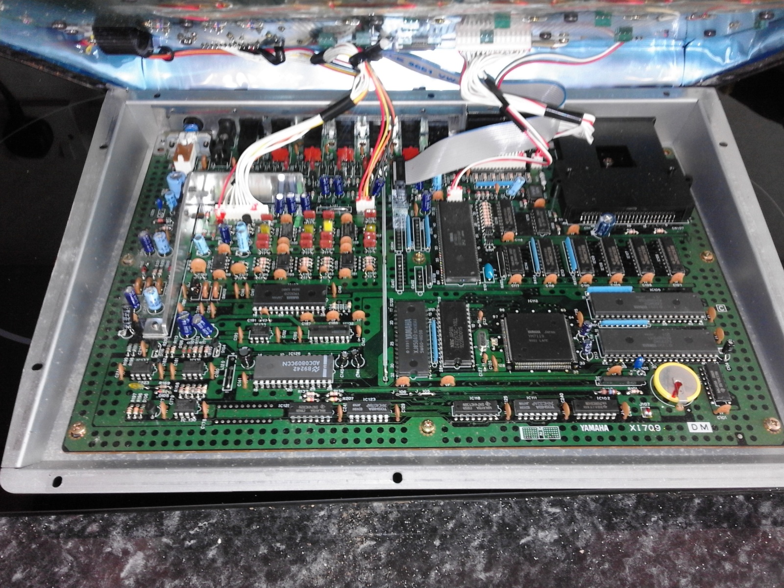
The view inside with the upper and lower boards still connected.
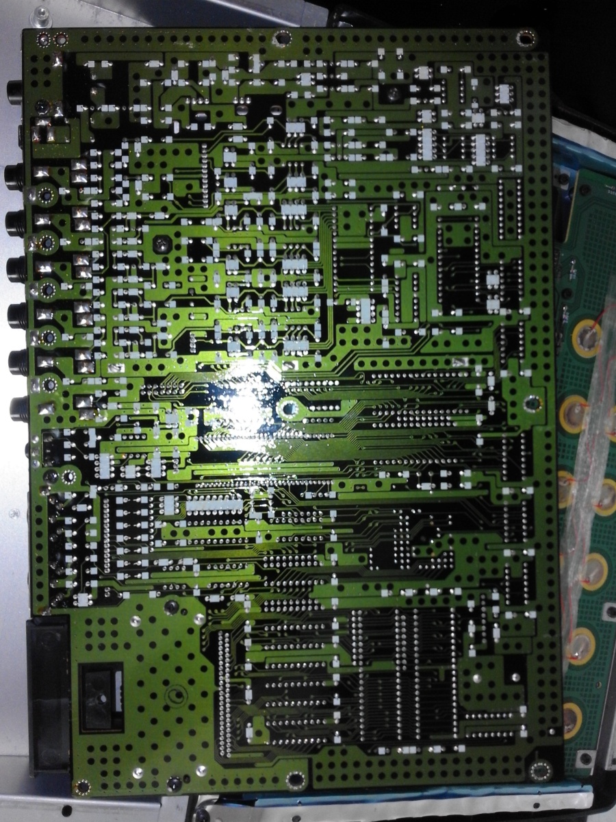
The underside of the mainboard.

Mainboard unscrewed #1.
Mainboard unscrewed #2.
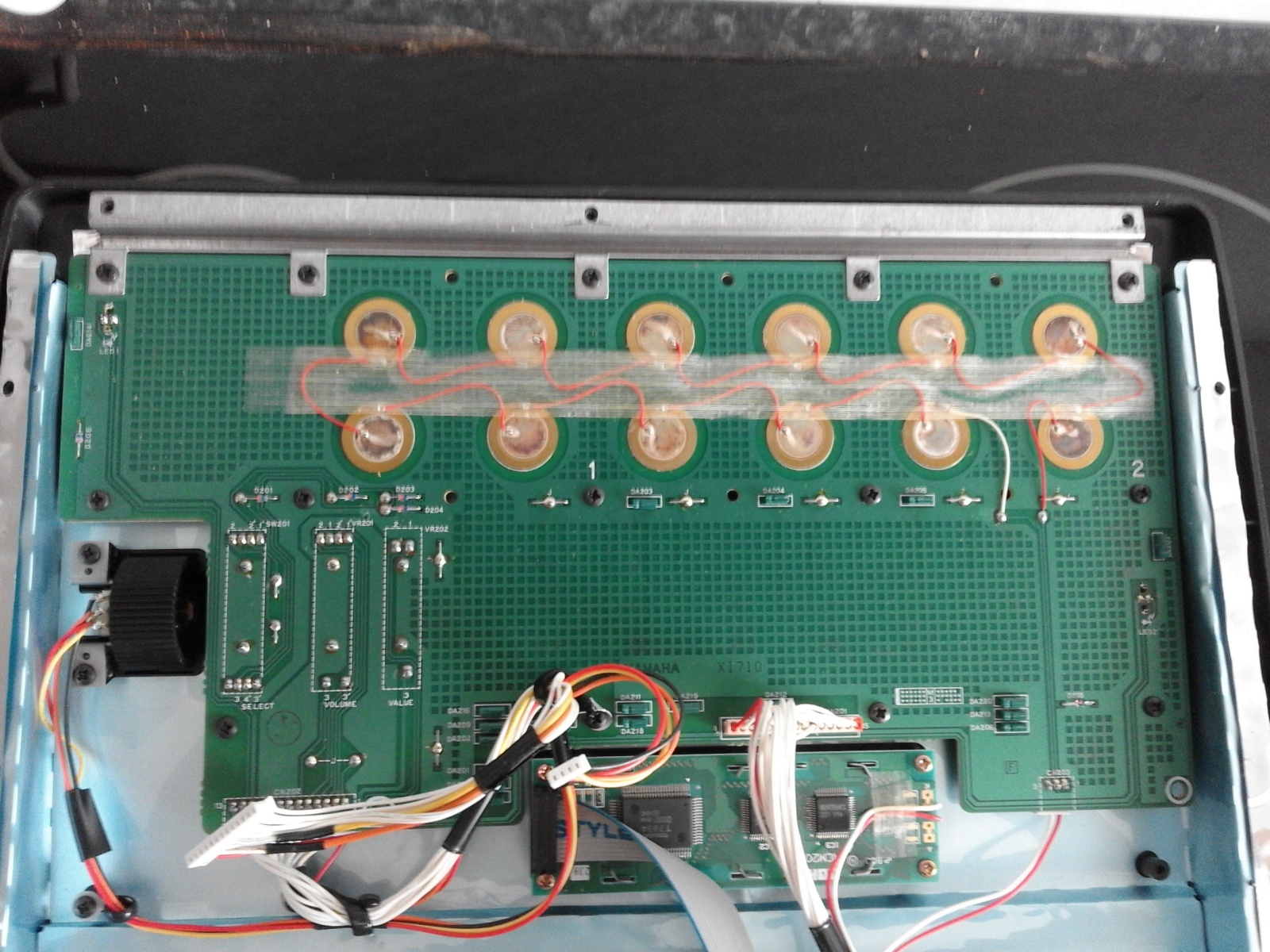
Underside of the upper board (holding the user controls). The underside of the twelve drum pads are visible to the top, jogwheel to the left.
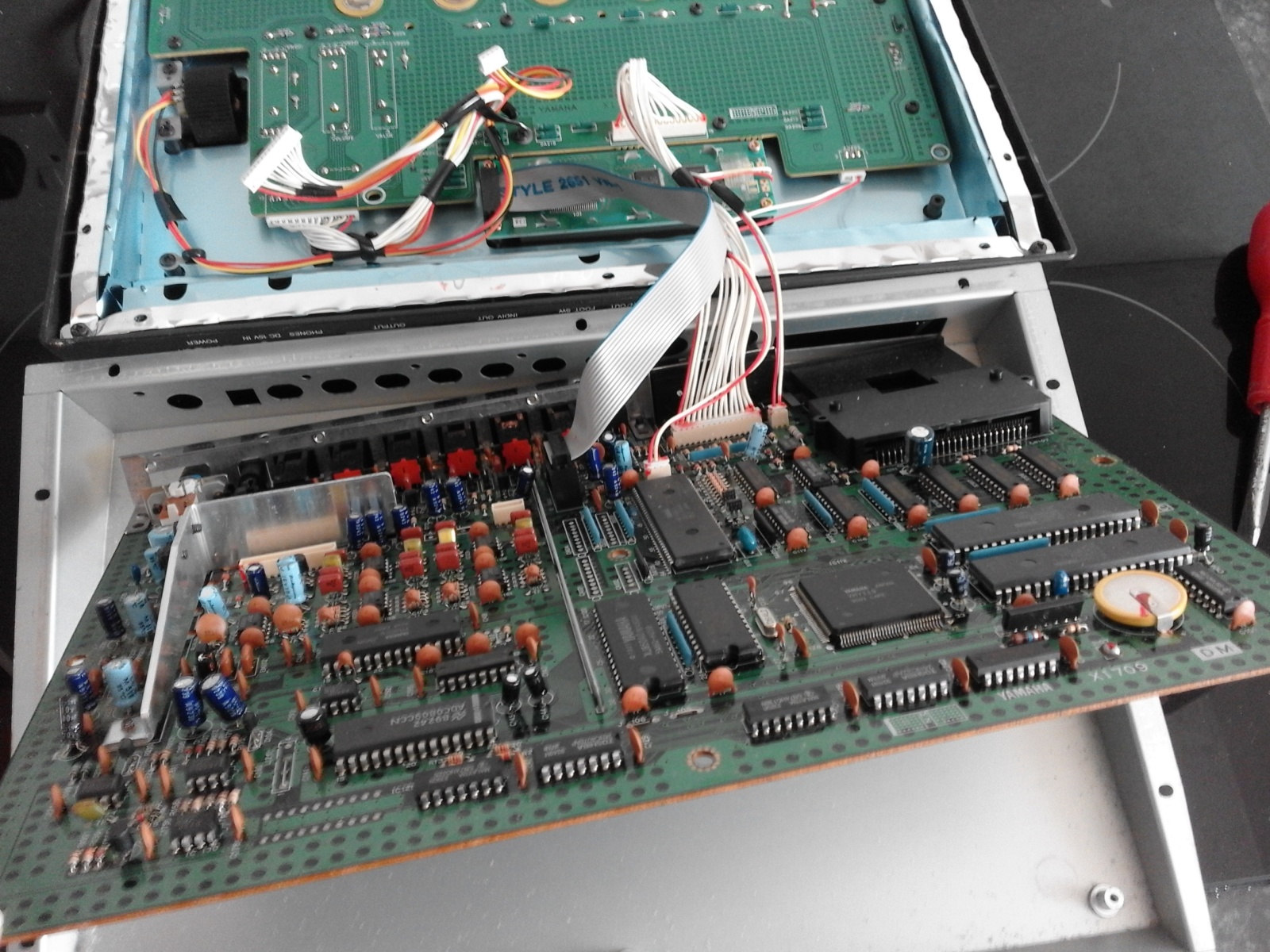
Mainboard removed from the base.
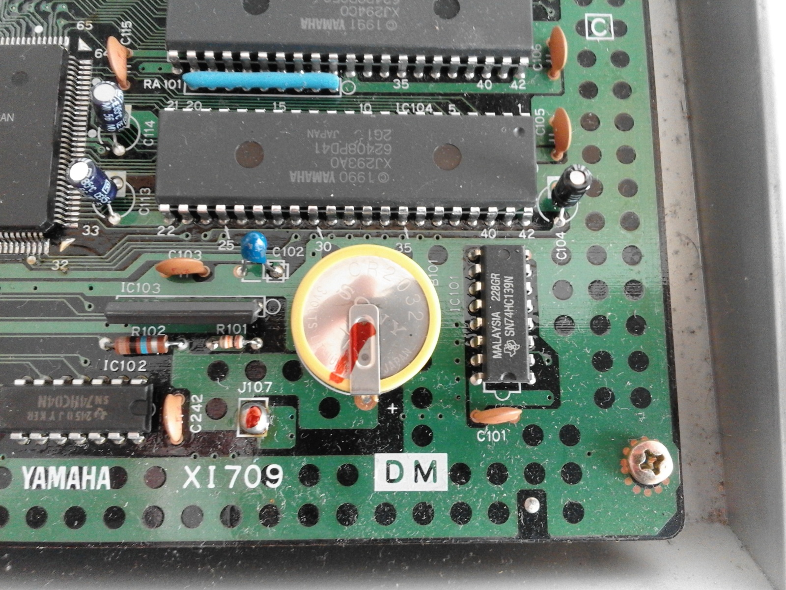
CR2032 battery close-up.