More on configuring MIDIsport 8×8/s MIDI ports

January 9th, 2021

Further to Configuring MIDIsport 8×8/s MIDI ports using a Windows 2000 VM, I’ve found the software/hardware communication to be very flaky, but I’d read that this was always the case.

After some failures, I found that trying to change port mappings and immediately use the hardware didn’t work for me while connected to the PC, using only external MIDI devices at least — the mappings didn’t seem to change and the unit wasn’t showing any activity.

Important: Note that I’m mainly using the MIDIsport 8×8/s as a standalone device with USB mode permanently selected on the front panel, and using a VM per the above post to configure its MIDI port mapping. I haven’t yet tried using it in conjunction with a DAW since getting port mapping to work.

Key point of this post, for standalone usage:

Shut down the VM after configuring and sending mappings to the MIDIsport, and disconnect the USB cable from the MIDIsport. It should then show LED activity with the current mapping after a few seconds (5-10 in my case).

Workflow

So far, my workflow to change ports appears to be this:

1) With MIDIsport 8×8/s running and connected to the PC, run the virtual machine;
2) Once up and running, take over the MIDIsport USB connection through the VM as per the earlier post;
3) Configure the ports as you wish via the Remote software;
4) Send the port configuration to the device (see below);
5) Exit the Remote software and SHUT DOWN THE VM;
6) For standalone use, disconnect the MIDIsport’s USB cable from the PC and wait 5-10 seconds for its LEDs to update*.

* Note that I haven’t yet tried to use with a DAW at this point, so not sure how that would work.

Regarding item 4), I don’t believe the port mappings are saved until you manually send them to the device, like so:

As far as setting up the ports go, it’s a bit of a mind-bender, but you are basically saying that for each of the physical MIDI Out ports, you want to receive data from the selected MIDI In ports only:

(Click for full-size image.)

In the above example, viewing the hardware itself, I have 3 physical MIDI inputs (highlighted in purple) and 5 MIDI outputs (highlighted in red) — please ignore the cable plugged into MIDI OUT 7 here!

For OUT 1 in the software, highlighted in amber in both hardware and software photos, I have selected the 3 MIDI Ins — so MIDI Out port 1 will receive input from my 3 controller devices plugged into MIDI IN 1, 2 and 3.

Compare the hardware and software images to understand how all 3 MIDI Ins are routed to physical MIDI Out port 1.

Once you ‘get’ this, the same has been repeated here for all 5 outputs — so each output MIDI device will receive input from all 3 input MIDI devices.

You can of course adjust to suit your setup, eg. you may only want MIDI Output 5 (let’s say this is a simple synth) to receive input from your master keyboard, connected to MIDI Input 1; in this case you would select only IN 1 against the OUT 5 line.

It’s important to note (this is where it really starts to blow one’s mind) that the port numbers are not MIDI channel numbers! This all affects the physical connections only — the device plugged into MIDI In 1, for example, may have MIDI channel 5 selected.

As long as the physical cables between the input device on channel 5 and the output device on channel 5 are mapped to ‘see’ each other, channel selection just works as normal.

Note that the MIDIsport 8×8/s can save 8 separate mappings, under “Current Patchbay Program” — this is program 1.

Note also that you can store your current mappings by clicking Save and inputting a name for the mapping. I believe to load you would hit Load, select a saved mapping, then Select Hardware to send the mapping to the device, per ‘Workflow’ item 4, above).

You select the programs on the hardware by holding the MIDI Reset button for a second; this shows the current selection by lighting all LEDs except the current program. (The current program will be unlit.)

Holding for longer will cycle through the programs, 1 to 8; keep it held until your desired program is unlit, then release.

Finally, as noted, once you’ve changed your mappings and sent to the device (per ‘Workflow’ item 4, above), shut down the VM to give USB control back to the main PC, and disconnect the USB cable from the MIDIsport. (Again, I have only explored standalone operation, so not yet sure how/if it works with a DAW… though it should.)

I did get into an odd state at one point, whereby attempting to reconnect the MIDIsport to the VM kept dropping the USB connection — my only solution was to reboot the host PC and MIDIsport. Make sure the MIDIsport is up and running before re-running the VM and connecting to the MIDIsport. Also note that the MIDIsport is notorious for needing to be running before external MIDI devices connect to it, so you may need to restart everything!

However, once you have set up a mapping that works, in most cases you probably won’t need to use the VM — just jump through the above hoops if you need to change the mapping.

After that, it should just work standalone with USB mode selected on the front panel and the USB cable disconnected. Make sure you’ve selected the right program number on the MIDIsport, as per the process above. It should be the one you edited in the software!

In short:

1) MIDIsport running first;
2) Run VM;
3) Configure ports;
4) SEND config to MIDIsport;
5) SHUT DOWN VM;
6) Disconnect MIDIsport’s USB cable;
7) MIDIsport should then work as a standalone device!

Items 4 and 5 are important after each remapping — it probably won’t work until you do this.

Again, my use case is currently running external devices/DAW-less only!

Configuring MIDIsport 8×8/s MIDI ports using a Windows 2000 VM

January 9th, 2021

This is a quick list of steps needed to gain access to the MIDIsport 8×8/s MIDI port mapping software, only available for Windows 9x/XP/2000.

This post assumes some familiarity with installing and using virtual machines; in my case, I’m using VirtualBox.

No guarantees this will work — I just wrote the steps quickly after getting it going!

The software will run on later versions of Windows, but won’t find the hardware due to different USB driver systems on Windows beyond XP.

You therefore need to use a virtual machine running an earlier OS, which can then access the MIDIsport directly via USB using the original drivers (at least in VirtualBox).

Download MS8x8_1010_web.exe from:

https://www.driverguide.com/driver/detail.php?driverid=211822

On that page, click the link I’ve highlighted in red here:

Click on Filename
Click Download the Driver File only
Complete Captcha
Click Continue
File should download

Install Windows 2000 in VirtualBox — this is something you’ll need to look into if not familiar, as it’s too detailed to go into here.

A suitable copy is available at:

https://archive.org/details/Windows2000ProfessionalSP4

You only need “Windows 2000 (no product key needed).iso” from the ISO files section, or via the torrent.

Click the ISO Image link then “Windows 2000 (no product key needed).iso”.

In the VM settings, enable Drag and Drop (use the Bidirectional option) under General -> Advanced tab.

Make sure USB 1.1 is enabled under USB. (I suggest using 1.1, not later.)

Install Windows 2000 in the virtual machine.

Once installed and running, drag and drop MS8x8_1010_web.exe onto the Windows 2000 desktop.

Shut down Windows 2000.

Turn on the Midisport 8×8/s; if it’s already on, turn it off and back on (important!). Note that I assume here its drivers are already installed in the host OS.

Make sure the Midisport is not being used by the host computer (eg. in a running DAW).

Start Windows 2000 VM.

Run MS8x8_1010_web from the virtual machine’s desktop to install the Midisport USB drivers and MIDIsport 8×8 Remote Panel software.

Select the Devices menu -> USB and then select the Midisport8x8 option to allow it to connect to the VM. (Note that this makes it inaccessible to the host computer, so the VM can take control directly.)

You can now run the Remote software via Start Menu -> Programs -> M-Audio Midisport 8×8 -> MIDIsport 8×8 Remote Panel.

If all went well… woo! Configure your ports!

See also my follow-up post on using the software/hardware setup, which is rather flaky, but apparently always was. You only need the VM to configure the port mapping anyway; the mapping(s) will be saved in the hardware once done.

More on configuring MIDIsport 8×8/s MIDI ports.

Yamaha RY30 Rhythm Programmer: drum machine battery replacement

December 20th, 2020

Faced with the now-common !CHANGE BATTERY! message on its display, I recently had to replace the battery in an RY30 drum machine I’d bought.

Having read a few posts on the subject, I decided I was reasonably confident of being able to do the swap, the hardest part of which involves de-soldering and soldering-in a new CR2032 coin-type battery — the type with tabs already fitted (you can’t just remove the existing battery as it’s not in a separate holder).

If you have even the most basic of soldering experience, this should be very straightforward… but do it at your own risk.

I have very little experience of soldering, and couldn’t find any decent pictures of the mainboard online, so I opened up the machine via a set of simple cross-head screws around the edge and rear, easily removed with a normal Phillips-type screwdriver, in order to take a look:

After removing all of the external screws, I carefully lifted off the top half of the case:

Note that the upper board is still attached by two cables, so you can’t move it far.

The cables’ sockets, with cables removed, are highlighted here:

Unplug the two cables from the mainboard and remove the top half.

I only have enough knowledge to be dangerous, so I was very wary of touching the capacitors, making it a little fiddly in terms of access, and the larger plug is made of a very flexible plastic, so it bends readily.

However, with a combination of flat screwdriver edges and swearing, both cables came free without too much trouble.

Here’s the underside of the upper board, showing the other end of the two cables. Note the underside of the jogwheel on the left, just out of interest.

With the rear of the unit facing away from you, the battery is located at the lower-right of the board (that round yellow thing!), and is secured by means of two legs soldered into the board.

Remove the seven brass screws holding the mainboard to the base of the unit:

Be careful with the one at the top right, inside the black data-card shield — try not to drop the screw inside!

Carefully slide the board towards you and it should come free — note that it is still attached by further cables, but this gives just enough access to replace the battery.

There’s nothing to stop you removing the remaining cables if you want better access, but do take some photos first!

I would suggest doing as I did, and giving the board and lower base a sweep with a soft camera brush if you have one, just to remove any dust that has accumulated over the past three decades!

With a soldering iron heated up to full operating temperature, I touched the base of each leg on the underside of the circuit board to melt the solder and they easily came free.

You can see the two large solder pads underneath the mainboard here, with plenty of space around them for the clumsy:

Here’s the board with battery removed:

My photos run out here, as I had to wait days for the battery to arrive, but refitting them was a case of adjusting the legs of the new battery holder so that they were reasonably ready for the pads, applying heat from the top and bottom of each hole.

With the first leg in approximately the right place, heating the underside of the pad for a few seconds allowed the leg to fall through easily; the same for the other leg. (Note that you should avoid heating the board for too long, and that the heat will spread along the circuit traces, so other areas can become very hot!)

Make sure you have the battery the right way round!

When I went to apply solder to the pads underneath, I found that the existing solder had already secured the battery in place and so frankly didn’t bother!

You may need to apply some solder to each underside pad, heating up the solder pad/leg and then simply touching the solder wire to it to get a small amount in place. Do one at a time, letting the first leg cool a little before continuing.

I re-fitted the two cables I unplugged earlier (they only fit one way — there is a slight indent on each so they should go in easily if inserted the right way round).

I connected the power supply up at this point and tested the display, also performing a factory reset: to do this, hold Dec, Pattern and PERC2 (L), then hit Stop/Continue at the prompt. This will clear all patterns and user data, leaving only the original manufacturer data in place.

The !CHANGE BATTERY! message should no longer appear, but any such problems may mean starting over, removing the two cables and perhaps turning the battery around, but it all went very smoothly for me.

Assuming no errors, screw the mainboard back in place. Here’s the earlier picture highlighting the brass screw locations:

Again, be careful with the screw at the top right, inside the black data-card shield — try not to drop it inside!

Note that it’s probably just as easy to solder in a CR2032 coin battery holder so you can more easily replace the battery in future… but I’d waited long enough and wanted to get it finished!

More photos

Hopefully these photos will start to appear in search results over time. Here are a few more that may be of more general use to anyone searching for inside shots of the Yamaha RY30 Rhythm Programmer…


The view inside with the upper and lower boards still connected.


The underside of the mainboard.


Mainboard unscrewed #1.


Mainboard unscrewed #2.


Underside of the upper board (holding the user controls). The underside of the twelve drum pads are visible to the top, jogwheel to the left.


Mainboard removed from the base.


CR2032 battery close-up.

Getting started with mojo3d: Something to see!

February 19th, 2019

Following on from the first part of this tutorial, where we created an empty scene (with nothing of interest to look at), we’ll now add a simple cube.


#Import "<std>"
#Import "<mojo>"
#Import "<mojo3d>"

Using std..
Using mojo..
Using mojo3d..

Class MyGame Extends Window
	
	Field scene:Scene
	Field camera:Camera
	
	Field cube:Model
	
	Method New  (title:String = "My Game", width:Int = 640, height:Int = 480, flags:WindowFlags = WindowFlags.Resizable)
		Super.New (title, width, height, flags)
	End
	
	Method OnCreateWindow () Override
		
		scene						= New Scene
		camera						= New Camera (Self)
		
		Local cube_box:Boxf			= New Boxf (-0.5, -0.5, -0.5, 0.5, 0.5, 0.5)
		Local cube_mat:PbrMaterial	= New PbrMaterial (Color.White)
		
		cube						= Model.CreateBox (cube_box, 1, 1, 1, cube_mat)
	
	End
	
	Method OnRender (canvas:Canvas) Override

		If Keyboard.KeyHit (Key.Escape) Then App.Terminate ()
		
		RequestRender ()
		
		scene.Update ()
		camera.Render (canvas)
		
	End
	
End

Function Main ()

	New AppInstance
	New MyGame
	
	App.Run ()
	
End

This code adds a field, cube:Model, which we’ll use to store a Model-type entity (a 3D entity with a mesh and other related features).

The cube setup (in OnCreateWindow, after the scene and camera setup) consists of three lines:

  1. Local cube_box:Boxf = New Boxf (-0.5, -0.5, -0.5, 0.5, 0.5, 0.5)

    This creates a Box object (specifically of floating-point type, as denoted by the ‘f’), used to define a volume. The values define the far corners of the box — view these as two lots of three x, y, z values, each set of three defining an offset in space, so -0.5 in each direction, following by 0.5 in each direction, forming two corners into which the box will fit.

  2. Local cube_mat:PbrMaterial = New PbrMaterial (Color.White)

    This line creates a material that will be applied to the cube. (PBR refers to a form of realistic rendering that we won’t go into here.) The PbrMaterial New method can take a colour parameter, and we’re using one of mojo’s built-in Color-class definitions.

  3. cube = Model.CreateBox (cube_box, 1, 1, 1, cube_mat)

    And finally, the CreateBox helper method provided by the Model class takes the box we just set up, uses 1 for each of the x, y, z segment values (how many times the box is split along each axis) and the material to be applied.

Run the code and… nothing appears!

That’s because the camera and the cube occupy the same point in space; we can’t see anything because the inside faces of the cube (normally viewed from outside) are hidden by default.

Add another line after the CreateBox line:

cube.Move (0, 0, 5)

This moves the cube 5 units along the z-axis, into the screen.

Run the code and the cube will appear.

Finally, for a bit of interest, add this line as the first line within OnRender:

cube.Rotate (1, 2, 4)

Run again and the cube will rotate, 1 degree around the x-axis per update, 2 around the y-axis and 4 around the z.

Experiment with the code — change the material colour to another defined in the Color class (see docs, but examples include Color.Red, Color.Lime, etc); also, change the speed of rotation, or set two axes to 0 to see the effect.

You can also change the size of the box definition to scale the cube.

Try moving the camera backwards instead of moving the cube forwards — hint: both Camera and Model are derived from the Entity class, which supplies the Move method. You’ll need to replace the reference to the cube with the reference to the camera, and supply a negative z-value in place of the 5 in order to move the camera back. (If you already know how to check for keypresses, try moving the camera back and forth in OnRender!)

You can download the source code for this tutorial at GitHub. This post is covered by the example, “2. Hello, Stuff.monkey2”.

Getting started with mojo3d: Creating a scene!

February 14th, 2019

This is a quick introduction to getting started with mojo3d.

You can download the source code for this tutorial at GitHub; if you don’t know how to use git, just click the big green Clone or download button and select Download ZIP. (You’ll also find a second source file, intended to form part of the next tutorial, that I’ve included in error, but what the hey! It may allow you to move on sooner anyway!)

It assumes you are comfortable with at least the basics of object-oriented programming, working with classes, fields, methods, and the like, but no more than that.

Here’s a simple program that implements just about the minimum necessary for a basic mojo3d application:

#Import "<std>"
#Import "<mojo>"
#Import "<mojo3d>"

Using std..
Using mojo..
Using mojo3d..

Class MyGame Extends Window
	
	Field scene:Scene
	Field camera:Camera
	
	Method New  (title:String = "My Game", width:Int = 640, height:Int = 480, flags:WindowFlags = WindowFlags.Resizable)
		Super.New (title, width, height, flags)
	End
	
	Method OnCreateWindow () Override
		
		scene				= New Scene
		camera				= New Camera (Self)
		
	End
	
	Method OnRender (canvas:Canvas) Override
		
		If Keyboard.KeyHit (Key.Escape) Then App.Terminate ()
		
		RequestRender ()
		
		scene.Update ()
		camera.Render (canvas)
		
	End
	
End

Function Main ()

	New AppInstance
	New MyGame
	
	App.Run ()
	
End

Imports

We start with a few imports — the standard library, the mojo graphics library, and the mojo3d library that sits ‘on top’ of mojo.

You will always need to import these three classes at a minimum.

We also specify that we are Using them, in order to avoid the need to prefix all class names; for instance, we can now use Camera instead of mojo3d.Camera.

Main Window class

Next, we create a new class that Extends mojo’s Window class, allowing us to implement our own functionality, and add more as needed, which includes a few fields and three methods: New, OnCreateWindow and OnRender. (Note that MyGame can be called whatever you like, and contains all of the features of the Window class.)

There are two fields present here, scene (of mojo3d’s Scene type) and camera (of mojo3d’s Camera type). These will be the minimum needed in order to create a technically working 3D environment.

The New method simply creates the game window, via the Window.New method (called via Super to refer to the ‘parent’ New method).

OnCreateWindow overrides the parent Window method and implements our required functionality, in this case assigning a new Scene to the scene field, and a Camera to the camera field.

The Scene class organises and manages the entire 3D world, including all entities (3D objects of the Entity class, of which more later).

The Camera class is a built-in class providing visibility into the 3D world. Cameras are a type of Entity class, too, which allows us to move them around, rotate them, etc, like any other 3D object.

OnRender is the final built-in class here, and is where the action takes place.

Here, we check for the Escape key being hit, in which case the application terminates.

We ask the application to update its view via RequestRender — this is required.

We call scene.Update in order to update the scene; this has no effect in this case, but later on it will become relevant and I would suggest adding it anyway. (It will handle physics and collision updates, among other things.)

Finally, we use the camera to render to a canvas. Note that the canvas reference is passed in automatically by mojo (see the OnRender parameter). Rendering to this canvas will result in our 3D view appearing on screen.

Main

The remainder of the code is the standard, required, Main function: it creates a new Application instance, creates a MyGame instance (our overridden Window class) and then runs the application.

Behold!

Run the code, and… oh! It’s a blue screen…

This is fine — we haven’t placed any entities into the scene yet, but this blue is the default Scene screen-clearing colour. (You can modify this using scene.ClearColor = Color.Black, or any of the other built-in colours — to see these, use the Color documentation by placing the cursor inside Color and hitting the F1 key twice. You can of course create your own colours, but we’ll keep things simple for now.)

The blue screen in fact shows that our scene is rendering correctly.

Next time, we’ll add something to look at! (See the GitHub note at the very start if you want to toy with the second source file in the meantime.)

Monkeying Around with mojo3d: Behaviours for simple entity management

January 8th, 2019

Following on from my last post, I am going to cover the final piece of the demo, the white self-deleting markers left by bullets striking the ground:

The source code zip file is in the previous post (scroll down a little), and remains unchanged. I just wanted to separate this out so you can see how useful it is to control non-physics entities too, in a really simple form.

WebGL Demo

Here’s the link to the web demo from that post — this new post relates to the little white markers left when bullets hit the scenery and how they simply remove themselves after a second:

Island WebGL Demo

As before, use Cursors to move, A & Z to speed up/slow down, plus Space to fire. Additionally, the plane now has yaw control, which is controlled via Q and E.

Behaviours, without physics

These ground markers are again defined as Behaviours, but this time without any physics elements — no rigid bodies or colliders this time!

As well as providing an easy way to attach physics to entities, Behaviours can also make management of non-physics entities really simple.

The only reference to this class is inside the BulletBehaviour’s Collided callback function, when the bullet is deleted from the scene. Just before it’s deleted, the bullet called MarkerBehaviour.Create, passing itself in as parent.

As covered in the previous post, this allows the new entity to automatically pick up the parent entity’s position and orientation, and we just need to remember to set its parent back to Null to ‘free’ it from the relationship.

In this case, that means a marker appears at the bullet’s final location and the Behaviour/component system handles the rest.

Note that there’s no other update or management code: the marker appears in the scene, then on each call to Scene.Update, its OnUpdate method is called.

Here, OnUpdate simply deletes the marker if it’s existed for more than one second. That’s it!

The rest of the code is the sprite creation, similar to the way bullets were set up — creating a global template sprite and simply copying it, the new copy picking up the parent bullet’s position and orientation, which will be where it collided with the ground. (The orientation is ignored, as sprites default to ‘billboard’ mode, remaining permanently upright. (You can modify this via Sprite.Mode and the SpriteMode enum options.)

Here’s the marker code in full:


Const MARKER_HEIGHT:Float = 10.0

Class MarkerBehaviour Extends Behaviour

	Global MarkerSprite:Sprite
	
	Field time_created:Int
	
	Function Create (parent:Entity)
	
		If Not MarkerSprite
			
			MarkerSprite			= New Sprite ()
			MarkerSprite.Visible	= False
			MarkerSprite.Scale		= New Vec3f (2.0, MARKER_HEIGHT, 1.0)
			
		Endif
		
		New MarkerBehaviour (MarkerSprite.Copy (parent))
	
	End

	Method New (sprite:Sprite)
	
		Super.New (Cast <Entity> (sprite))
		
		AddInstance ()
		
		sprite.Parent	= Null
		sprite.Visible	= True
		
		sprite.Move (0, MARKER_HEIGHT * 0.5, 0)
		
		time_created	= Millisecs ()
		
	End
	
	Method OnUpdate (elapsed:Float) Override
	
		If Millisecs () - time_created > 1000
			Entity.Destroy ()
		Endif
		
	End
	
End

One minor quirk: I was experimenting with passing in a Sprite instead of a plain Entity for the New method, hence there is a cast to Entity for the Super.New call. This wasn’t really necessary, but as with previous classes at least shows you can do things in different ways. Just pick what suits you and be more consistent than this!

Now you can place thousands of entities into your game scene and leave them to their own devices — no other management code or lists of entities needed!

Just remember to call Scene.Update in your OnRender method. (See island.monkey2, the main code file.)

Note on ‘missing’ markers in demo

You may notice that markers sometimes don’t appear, particularly on steep hills or sides of buildings.

My best guess is that they are simply buried inside the geometry, the collisions being detected part-way through the steep hillsides, etc, and the steeper the hillside, the less chance the marker will protrude through the ground. Setting the ground alpha to partly transparent shows all markers appearing, so I believe they’re simply inside. (A possible alternative explanation is that the island model geometry is a little messed-up; this can even be seen in normal demo use, with floating walls and cut-off slopes here and there, and the triangles do look a little odd, and possibly even flipped in places, when ground alpha is set to < 1.0.) I suppose it would be possible to manually calculate the correct vertical position using the mesh geometry and adjust the markers accordingly, but of course it's not overly-important for this demo!

Monkeying Around with mojo3d: more Behaviours… with bullets!

January 6th, 2019

The last post was mainly about rearranging the code, wrapping up models and rigid bodies into the Behaviour classes they belonged in.

This post is a little more fun, adding bullets and simple ground markers that delete themselves after a second.

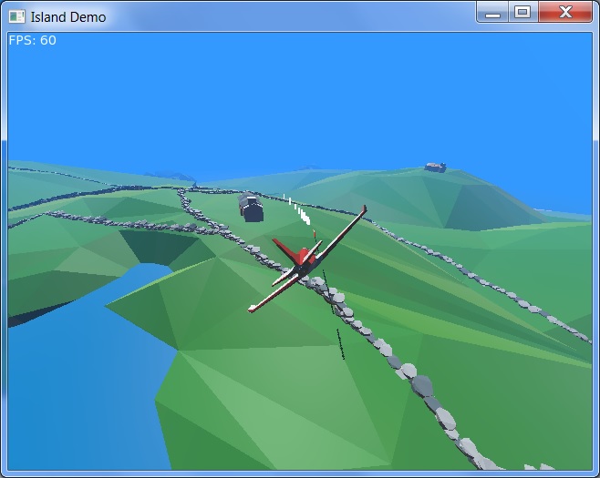
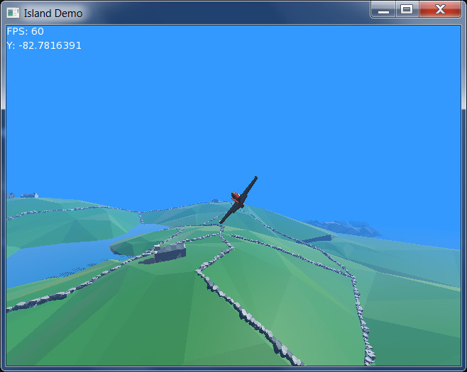
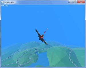
The bullets are remarkably hard to capture in a screenshot, for reasons too boring to go into, but they look way better in-game!

WebGL Demo

I’ve also added a WebGL demo here so you can try online:

Island WebGL Demo

As before, use Cursors to move, A & Z to speed up/slow down, plus Space to fire. Additionally, the plane now has yaw control, which is controlled via Q and E.

Plane changes

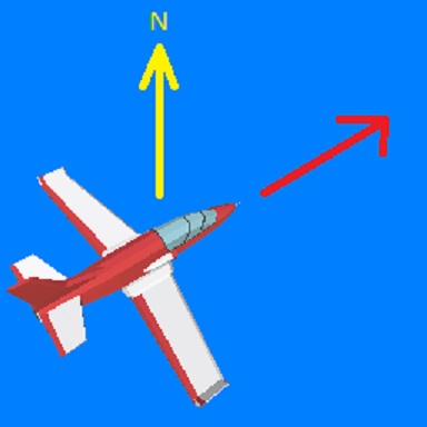
There have been a few changes to the plane’s physics, most obviously in the addition of yaw controls, but also in that the plane will now pitch and yaw when banking. This means that banking causes the plane to turn as a real plane does (the pitch pulls the banked plane around) and also starts losing height, via yaw.

It’s far from a proper simulation, but still feels believable enough for the most part, at least in terms of a simple arcade-style game.

Interestingly, adding the pitch and yaw during banking made it much easier to target and hit the buildings, as it behaves much more like a real plane now, so movement is more predictable. (It’s still pretty difficult, mind!)

It’s hard to believe the underlying physics representation is still just a simple sphere!

Source code — what you’ll need

As usual, the intention of these posts is that you scroll through the code at the same time, in order to see what each section is doing.

Download the code and media below before continuing. Open up island.monkey2 in the default Monkey2 editor, Ted2Go, and additionally, bullet.monkey2 and marker.monkey2. (The easiest way is to simply drag and drop all three files into the Ted2Go window.)

IslandDemo source and media [Note that this is NOT a secure server, but the zip file contains only source code — text — and the 3D media. Run it through your virus scanner for peace of mind!]

Double-click the island.monkey2 tab to make it the default build file and hit F5, or the Run icon, to try it out.

Switch to the bullet.monkey2 tab, where you’ll find the following extract:


Const BULLET_LENGTH:Float	= 15.0
Const REMOVE_DISTANCE:Float	= 750.0

Class BulletBehaviour Extends Behaviour

	Global BulletModel:Model
	Global LastBullet:Entity
	
	Field start_pos:Vec3f
	
	Function CreateBullet (parent:Entity)
	
		If Not LastBullet

			BulletModel			= Model.CreateCylinder (0.33, BULLET_LENGTH, Axis.Z, 8, New PbrMaterial (Color.White))
			BulletModel.Visible	= False

			New BulletBehaviour (BulletModel.Copy (parent))

		Else
			If LastBullet.Position.Distance (parent.Position) > BULLET_LENGTH * 2.5
				New BulletBehaviour (BulletModel.Copy (parent))
			Endif
		Endif
		
	End
	
	...

We have two constants, BULLET_LENGTH and REMOVE_DISTANCE, with some default values defined.

The ‘bullets’ in this example are really just stretched cylinders, intended to look similar to tracer streams, and their collision bodies are the same for simplicity.

  • BULLET_LENGTH sets the ‘length’ of each bullet;
  • REMOVE_DISTANCE allows us to remove bullets from the scene after travelling a given distance.

This means our bullets are in fact 15m (50ft) long — a fine example of the fraudulent hand-waving peculiar to creating games!

The bullets will travel for 750m before being removed from the scene, so as to limit the number of active physics bodies and related 3D entities.

The start_pos field holds the bullet’s starting position in a Vec3f, which is a 3D ‘vector’ of floating-point type — a structure that holds the x, y, z elements of a three-dimensional position in a single value. (The f in Vec3f refers to float).

Don’t be afraid of Vec3f if this is new to you! We will be assigning start_pos with the bullet model’s position later on, and it’s as simple as:

start_pos = Entity.Position

We can therefore easily store the entity’s 3D position in a single variable.

The behaviour class definition follows, including two class global variables holding Model references:

  • BulletModel: a base model we can just copy for every bullet;
  • LastBullet: a reference to the last bullet fired. This allows us to avoid firing new bullets until the last bullet has travelled a given distance, a simple way of controlling the fire rate.

LastBullet was originally of Model type, but I changed this to Entity just to avoid casting from Entity later on, in the OnStart method. It’s not important, just shows different options; you can decide for yourself how you prefer to handle this in your own projects — just be more consistent than I have here!

I’ve chosen in this case to create a globally-accessible CreateBullet function from which we’ll create new bullets in the main source file. In island.monkey2, you’ll find this function called within OnRender. It passes in the PlaneBehaviour’s Entity reference, for reasons we’ll see shortly:

If Keyboard.KeyDown (Key.Space) Then BulletBehaviour.CreateBullet (plane.Entity)

The main reasons for doing it this way, rather than calling New BulletBehaviour directly, are:

  1. It shows that we can wrap the bullet model into the BulletBehaviour class, as an alternative to the way the plane model was set up, where we loaded the model in the main OnCreateWindow function and passed that in to New PlaneBehaviour;
  2. but more importantly, it allows us to check the distance between the last bullet fired and the ‘new’ bullet, prior to creating it, and to keep all of this checking bundled within the BulletBehaviour class. (We don’t want to create a new bullet if the last bullet hasn’t travelled far enough.) This avoids the need for checking to be implemented from the call site — the location from which a function is called — and also does away with the need to hold a reference to the last bullet fired inside the main code.

Instead, CreateBullet will only call New BulletBehaviour after performing these basic checks.

CreateBullet receives a parent entity, which will be the plane model, then checks if this is the first call to CreateBullet, in which case LastBullet will not yet exist; if LastBullet doesn’t exist, it creates the base model, BulletModel, and spawns the first bullet.

The New BulletBehaviour call sets up LastBullet, so that on the next call (and all subsequent calls), the Else block will be called instead, carrying out a distance check prior to creating a new bullet.

(In fact, it would probably more sensible to rearrange things so that the less-common case falls within the Else block, ie. creation of the bullet! However, it’s not speed-critical, so I’ll just leave as-is — I think it’s a little clearer as to what is happening this way.)

Once created, the base BulletModel will be copied and modified for each new bullet fired.

BulletModel is a simple cylinder model, with 0.3m (1ft) radius to enhance visibility (more cheating!), and the 15m length defined earlier, aligned along the z-axis (so orients ‘into’ the screen, rather than vertically or across). It has 8 segments to keep it simple and a basic white material.

As this is just a base model to be copied for each actual bullet, it’s hidden from display so as not to leave it floating in the scene.

In the usual case, where BulletModel and LastBullet have already been created, we check the last bullet’s position relative to the plane:


	If LastBullet.Position.Distance (parent.Position) > BULLET_LENGTH * 2.5
		New BulletBehaviour (BulletModel.Copy (parent))
	Endif
		

Notice again that we have a handy reference to each entity’s Position property; Position is a Vec3f, which in turn has a handy Distance method available.

To see this, click on the word Position and press F1 twice: this will open up the Position property documentation. Click on std.geom.Vec3f, then on Vec3 (the base 3D vector class). This will list all of the data and methods available to Vec3f. You’ll find Distance listed further down.

Here, we are using LastBullet’s Position Vec3f to call the Distance method, and we simply pass in the plane’s Position for comparison, receiving a single distance value as a result.

From trial-and-error, I’ve chosen to spawn a new bullet only if the last bullet is over 2.5 times the bullet length away from the plane. If not, nothing happens and the function is done — no bullet is created.

This initialisation could be simplified greatly by having a specific externally-called function that sets up BulletModel (which would have to be manually called in the main code file prior to using New BulletBehaviour), but I preferred having everything all wrapped up here — and a single test for LastBullet’s existence really isn’t going to be having any practical effect on processing speed.

To clarify the New BulletBehaviour call here:

New BulletBehaviour (BulletModel.Copy (parent))

Here we pass in a copy of the base BulletModel — the Model class has a handy Copy function to create a standalone copy of a model.

Note that Entity.Copy cannot copy entities with attached components, such as physics bodies, hence BulletModel is nothing more than a basic model with no rigid body or collider.

The parent reference was passed in as CreateBullet’s only parameter, set as the plane model when calling from the main source file.

One really handy aspect of creating an entity with a specified ‘parent’ entity is that it picks up the parent’s position and orientation upon creation — so our bullet is already aligned correctly with the plane.

You could instead pass in the plane’s position and orientation, and use these to align the bullet, but I find the parent solution much more convenient.

The only downside to this method is that you need to remember to remove the parent relationship once in position, so as not to affect the bullet’s position or rotation when you modify the plane. We’ll be doing this inside BulletBehaviour’s OnStart method.

Using OnStart

I’ve updated both the plane and bullet classes to move the physics body setup into the OnStart method, instead of doing this during New.

The reason for this was that bullets were causing the program to crash when spawned: it turns out OnStart can be called before New has completed!

Although the rigid body was set up during New, OnStart had already been called by Scene.Update before this happened.

As OnStart makes reference to the body, which didn’t yet exist, the program would crash. Carrying out the physics setup in OnStart avoids this, since we’re making sure the body exists before we reference it.

I don’t fully understand why this works the way it does, but just bear in mind that Scene.Update may call OnStart before New has completed! Just follow this arrangement in your Behaviours to avoid the same fate: leave the New method as a simple Super.New and AddInstance.

Here’s the beginning of OnStart:


	Method OnStart () Override
	
		Entity.Visible					= True
		Entity.Move (0, -2, 15)

		Local bullet_velocity:Vec3f		= Entity.Parent.RigidBody.LinearVelocity + (Entity.Basis * New Vec3f (0, 0, 300))
		
		Entity.Parent					= Null
		
		Local collider:CylinderCollider	= Entity.AddComponent <CylinderCollider> ()
		
			collider.Radius				= 1.0
			collider.Axis				= Axis.Z
		
		...

Entity here is a copy of BulletModel, which was hidden upon creation, so we first make it visible.

The bullet will be sitting at the plane’s position by default, with the same orientation, because the plane model was specified as its parent upon creation in CreateBullet. Any movement will currently be relative to the plane’s position and orientation, so we just move it down 2 metres and ahead 15 meters, as judged by simple trial and error.

Next, we are storing the linear velocity of the parent entity’s rigid body (the plane’s body), so that the bullet carries the same speed, to which we are adding a further forward vector, which is modified by the bullet’s Basis (orientation):


	Local bullet_velocity:Vec3f		= Entity.Parent.RigidBody.LinearVelocity + (Entity.Basis * New Vec3f (0, 0, 300))

'

After setting an independent entity’s position and orientation via a parent, remove the parent!

We then, importantly, remove the parent/child relationship between bullet and plane, by setting the entity’s parent to Null.

Note that we stored the parent entity’s speed before removing this relationship — Entity.Parent is no longer available.

We’ll apply bullet_velocity via ApplyImpulse shortly…

Next comes the collider and rigid body setup, as usual, but in this case we have an additional feature:


		Local collider:CylinderCollider	= Entity.AddComponent <CylinderCollider> ()
		
			collider.Radius				= 1.0
			collider.Axis				= Axis.Z
		
		Local body:RigidBody			= Entity.AddComponent <RigidBody> ()
			
			body.Collided				=	Lambda (other_body:RigidBody)
												
												MarkerBehaviour.Create (Entity)
												
												Entity.Destroy ()
												
											End

			...

Notice that body.Collided weirdness!

Rigid Body Collisions

This is how the Bullet Physics SDK gives us collision responses — by way of a callback function.

In this case, the function is a ‘lambda’ function, which is defined ‘inline’ without a name, rather than separately (as with standard functions), and, importantly, lambda functions are able to access variables within the current scope: that’s why we can access ‘Entity’ here, inside the function.

Don’t worry about the details, just define it like so and fill in what you want to happen when this body collides with another:


Lambda (other_body:RigidBody)
												
	' Response actions go here!

End

This code when be called upon collision, every time the body is touching another. Note that the other_body parameter is filled in by the physics system, allowing you to retrieve that body’s information.

The function will be called continuously while in contact, eg. while a ball is rolling along the ground, not just at the point of collision.

In our case, we create the ground marker (which I’ll cover in a separate post) and destroy the bullet:


	MarkerBehaviour.Create (Entity)
	
	Entity.Destroy ()

When the bullet entity is destroyed — removed from the 3D scene — so are all of its components, which in this case means automatic destruction of both collider and rigid body. We don’t need to do anything more than destroy the entity.

The other_body parameter gives us a reference to the other body involved in the collision. For multiple colliding bodies, this function will be called against each one in turn. By default, we collide with all other rigid bodies, and their responses are handled automatically.

(I’ll probably go into collisions more in a later post, including the grouping of different types of bodies, and filtering these for different responses in the Collided lambda function.)

You can, by the way, add further collision callback functions if you want. Try uncommenting these lines in the code:

'			body.Collided				+=	Lambda (other_body:RigidBody)
'												Print "Hi"
'											End

For each collision, this extra function will additionally print “Hi” to the console. Note the += syntax here, which adds to the ‘list’ of functions to be called.

Nearing the end, we set the start position (as noted earlier), set LastBullet to the bullet we’ve just created, and set the entity’s colour randomly to one of four built-in colours:


		start_pos						= Entity.Position
		
		LastBullet						= Entity
		
		Select Int (Rnd (4))
		
			Case 0
				Entity.Color			= Color.White
			Case 1
				Entity.Color			= Color.Yellow
			Case 2
				Entity.Color			= Color.Orange
			Case 3
				Entity.Color			= Color.Red
			
		End
		

Finally, there’s a tricky little bit of casting required in order to set the ’emissive factor’ in the bullet’s material, which here gives the bullets a sort of glowing effect:


		Local model:Model				= Cast <Model> (Entity)
		Local pbrm:PbrMaterial			= Cast <PbrMaterial> (model.Material)

			pbrm.EmissiveFactor			= Entity.Color

		Entity.RigidBody.ApplyImpulse (bullet_velocity)

I broke this down into a couple of steps for easier reading:

  1. Cast the behaviour’s Entity reference to a Model: basic entities don’t have PbrMaterials, which provide more advanced rendering functionality than the plain Material an entity has. Models can use PbrMaterials, and we need this type of material to use EmissiveFactor;
  2. The material needs to be cast to a PbrMaterial in order to access EmissiveFactor, and for simplicity we are assigning a PbrMaterial handle here;
  3. Now we can set the EmissiveFactor: this takes a Color, and we’re just using the entity’s existing colour (which we just set), causing the material to ‘glow’ in this colour, preventing shadows from appearing as they naturally would, and thereby giving a nice glowing effect.

OnUpdate

Lastly, we have OnUpdate, applied on each physics update (60 frames per second by default, independent of the actual FPS):


	Method OnUpdate (elapsed:Float) Override
		
		Entity.RigidBody.ApplyForce (New Vec3f (0.0, -40.0, 0.0))
		
		If Entity.Position.Distance (start_pos) > REMOVE_DISTANCE
			Entity.Destroy ()
		Endif
		
	End

The first line is a cheat! The bullets weren’t falling as much as I wanted them to, so I manually applied a force to push them down more than gravity is doing by default.

We then simply test how far the bullet has travelled from its start position; if it’s travelled more than REMOVE_DISTANCE (750 metres, set at the top of the file), the bullet is destroyed. Simple!

In summary

There’s a lot here to pick up, but just take it a little at a time and compare constantly with the actual source code.

I’ll address the final aspect of the demo, the ground markers, in a follow-up shortly. They’re extremely simple in comparison, but show an easy way to use Behaviours to manage non-physics objects too.

Monkeying Around with mojo3d: wrapping physics behaviours

December 16th, 2018

This post continues on from Monkeying Around with mojo3d: physics behaviours.

As always, the intention of this post is that you scroll through the code at the same time, in order to see what each section is doing.

Note that this time, I have moved the PlaneBehaviour class into its own file, to more accurately reflect how a real-world project would be organised.

Download the updated code and media below before continuing:

IslandDemo source and media [4.6 MB; note that this is NOT a secure server, but the zip file contains only source code — text — and the 3D media. Run it through your virus scanner for peace of mind!]

Open up both island.monkey2 and planebehaviour.monkey2 in the Ted2Go editor, and double-click the island.monkey2 tab to set it as build file; a litte + sign will appear in the tab to make this clear. Making island.monkey2 the build file means that even if you’re tweaking the PlaneBehaviour class, you can just hit Ted2Go’s Run command (F5 or the rocket icon) to build island.monkey2.

You can double-click the tab again to de-select island.monkey2 as the build file. When no file is set as the build file, whichever tab you hit Run from will be treated as the build file.

Splitting into separate files makes the main file much simpler, and makes jumping between the PlaneBehaviour definition and the main code a simple switch between tabs, rather than scrolling up and down between class and main code.

Importing Code

Note that the main code file now features this line near the top to import the PlaneBehaviour file, making the PlaneBehaviour class accessible to island.monkey2:

#Import "planebehaviour"

You can specify the full name, like so, if you prefer:

#Import "planebehaviour.monkey2"


Before we proceed, a ‘Mea Culpa’…

In the last post, I ended by saying:

In the real world, you probably wouldn’t want to have the collider and rigid body setup carried out in the main body of the code, but instead do this within the OnStart method of the Behaviour so as to encapsulate all of the plane’s data.

As the New method of Behaviour only allows the passing-in of an entity parameter, this can make things a little tricky, so I’ll address my solution to this in the next post.

While the first line is true, the second line is… well, an embarrassing mistake!

I had thought that the Behaviour class’s New method could only take the default entity:Entity parameter listed in the Monkey2 documentation.

However, PlaneBehaviour extends Behaviour, and we can in fact define our own overridden New methods!

What this means, in short, is that we can easily pass in any parameters we want to PlaneBehaviour, and therefore set everything up inside the PlaneBehaviour class, instead of partly in the main program and partly inside PlaneBehaviour (without the trickery I had intended to demonstrate!).

The Old

Previously, the plane was set up outside the PlaneBehaviour class, in the main program (within OnCreateWindow), like so:


		Local plane_size:Float					= 16.83 * 0.5
		Local plane_box:Boxf					= New Boxf (-plane_size, -plane_size, -plane_size, plane_size, plane_size, plane_size)
		
		Local plane_model:Model					= Model.Load ("asset::1397 Jet_gltf_3B3Pa6BHXn1_fKZwaiJPXpf\1397 Jet.gltf")

			plane_model.Mesh.FitVertices (plane_box)
			plane_model.Mesh.Rotate (0, 180, 0)
			
			plane_model.Move (0.0, 5.0, 0.0)

		' Cull hidden tris...
		
		For Local mat:Material = Eachin plane_model.Materials
			mat.CullMode = CullMode.Back	
		Next

		' Physics setup...
		
		Local plane_collider:SphereCollider		= plane_model.AddComponent <SphereCollider> ()

			plane_collider.Radius				= plane_size * 0.6
		
		Local plane_body:RigidBody				= plane_model.AddComponent <RigidBody> ()

			plane_body.Mass						= 10954.0
			plane_body.Restitution				= 0.5
			plane_body.AngularDamping			= 0.9
			plane_body.LinearDamping			= 0.1
			plane_body.Friction					= 0.0

		plane									= New PlaneBehaviour (plane_model)

This is not ideal, as it places all of the technical setup in the main body of the code, reducing the simplicity of setting up another plane, or several planes, as you have to define a collider and rigid body every time. When this complexity is all wrapped-up into the class, setting up a new plane can be greatly simplified, requiring nothing more than a simple call to New PlaneBehaviour.

The New

In this revised version, the setup code simply loads the model and sets up some basic values for physics processing:


		Local plane_model:Model					= Model.Load ("asset::1397 Jet_gltf_3B3Pa6BHXn1_fKZwaiJPXpf\1397 Jet.gltf")

		' Core values for physics...

		Local mass:Float						= 10954.0
		Local roll_rate:Float					= 550000.0
		Local pitch_rate:Float					= 250000.0
	
		' And pass plane_model into PlaneBehaviour, where physics
		' will be applied...
		
		plane = New PlaneBehaviour (plane_model, mass, roll_rate, pitch_rate)
		

The model is loaded and then a few core values are set up — mass, roll rate and pitch rate (technically single elements of the torques that will be applied to specific axes).

Finally, New PlaneBehaviour is called, passing in:

  • plane_model
    the model loaded and set up earlier;
  • mass
    the mass, defined above as 10954 kg;
  • roll_rate
    the roll rate (element of torque to be applied to the z-axis);
  • pitch_rate
    the pitch rate (element of torque to be applied to the x-axis).

These values are arbitrary — just the values I chose to pass in — but you could easily amend this to suit yourself.

For example, if you decided to simply hard-code the mass, roll rate and pitch rate as fixed values inside the class, you could remove these elements (from both the call here, and the PlaneBehaviour New definition) and simply set them inside PlaneBehaviour’s New method.

The idea here is simply to demonstrate the ability to pass in changeable values to New PlaneBehaviour.

In a professional setup, other programmers might be calling your New PlaneBehaviour method to set up enemy aircraft, for example.

If you’ve hard-coded these values inside PlaneBehaviour, anyone (including you!) trying to tweak these for different types of enemy plane would have to edit the PlaneBehaviour class, affecting all other planes in the game! By allowing these values to be passed in per-plane, they can be defined by the calling programmer without affecting any other aircraft behaviours.

Down inside PlaneBehaviour, we’ve gone from this:


	Method New (entity:Entity)
		
		Super.New (entity)
		AddInstance ()

	End
	

… to something that looks much more complex, but is in fact much the same code as before, just moved from outside the class to inside the class:


	Method New (entity:Entity, mass:Float, roll_rate:Float, pitch_rate:Float)
		
		Super.New (entity)
		
		AddInstance ()

		Local plane_size:Float					= 16.83 * 0.5
		Local plane_box:Boxf					= New Boxf (-plane_size, -plane_size, -plane_size, plane_size, plane_size, plane_size)
	
		' Get a Model-specific handle to the entity:
		
		Local plane_model:Model					= Cast <Model> (entity)
		
		plane_model.Mesh.FitVertices (plane_box)
		plane_model.Mesh.Rotate (0, 180, 0)
			
		plane_model.Move (0.0, 5.0, 0.0)

		' Cull hidden tris...
		
		For Local mat:Material = Eachin plane_model.Materials
			mat.CullMode = CullMode.Back	
		Next

		' Physics setup...

		Local plane_collider:SphereCollider		= entity.AddComponent <SphereCollider> ()

			plane_collider.Radius				= plane_size * 0.6
		
		Local plane_body:RigidBody				= entity.AddComponent <RigidBody> ()

			plane_body.Mass						= mass
			plane_body.Restitution				= 0.5
			plane_body.AngularDamping			= 0.9
			plane_body.LinearDamping			= 0.75
			plane_body.Friction					= 0.0

		roll_torque								= roll_rate
		pitch_torque							= pitch_rate
		
	End
	

We’re now loading and adjusting the model here in PlaneBehaviour.New and doing setup of the physics collider and rigid body where they really belong. (The code remains much the same as it was before, when it was defined in OnCreateWindow, but is now properly encapsulated within the class.)

The first two lines remain as before, creating a Behaviour from the entity (plane model), and placing it into the scene; just treat these as necessary boilerplate lines, as mentioned last time — copy and paste!

We’ve then moved all the loading and positioning code into the class itself, setting up the plane’s size, bounding box and adjusting the mesh to fit, then positioning the plane at its start point.

One line that will almost certainly need explanation is this, just after the size and bounding box definition:

Local plane_model:Model					= Cast <Model> (entity)

Behaviour requires that an Entity object be passed in, Entity being the ‘lowest common denominator’ class of 3D object.

All 3D objects in mojo3d are variations of the Entity class: Model, Light and Camera are all extended versions of class Entity (each of these extends the Entity class), but each has its own domain-specific functionalities, some of which would include:

  • Model: Holds a mesh and materials to be applied to the mesh;
  • Light: Holds a direction, range and colour;
  • Camera: Holds near and far ranges, field of view, ability to render to a Canvas, etc.

Entity, on the other hand, gives us the core positioning and rotation methods used by Model, Light and Camera, as well as many other basic functionality.

Because Behaviour.New only gives us a reference to an entity (not a Model, or a Camera, for example), we need to ‘cast’ the entity to the specific class of entity we expect to operate upon; in this case, a Model.

We create a local variable to hold this Model reference:

Local plane_model:Model ...

… and call Cast (entity) with the modifier to receive the type of entity required:

... Cast <Model> (entity)

The plane_model variable therefore now holds a reference to the entity upon which we can call Model-specific methods.

After setting up the model, we cull any backfacing triangles, as before, and then set up the collider and rigid body — again, as before.

Lastly, the renamed roll_torque and pitch_torque fields (which are still technically misnamed!) are set up from the roll_rate and pitch_rate parameters passed in.

In Summary

  • Use the extended Behaviour’s New method to get the entity (usually a model*) and any required data into the class, and set up your model and its physics collider and rigid body. (There is certainly a case to be made for leaving the model adjustment outside of the class, but this will be down to your own judgement.)* Note that there’s no reason you can’t pass in other types of entity, such as a camera you’d like to be physically controlled.
  • Use OnStart to do any initial startup processing; in this case, we get a handy typing shortcut to the physics body and set the plane’s initial impulse force.
  • Use OnUpdate to process any custom updates, such as applying player input forces to the entity, as happens here.

Other Tweaks

  • The rigid body’s LinearDamping value has been tweaked to 0.75; previously, in a tight turn, the plane’s rotation appeared unrealistically tight. This looks a little better.
  • The plane’s collider visualisation (the semi-transparent sphere you could enable) has been removed.
  • Support functions have been to aerialcamera, which is the only place they’re used.

This post has probably been rather technical, but just look at the code itself and cross-reference here for anything you don’t quite ‘get’!

In the next post, I’ll demonstrate the power of Behaviours a little more clearly by adding bullets, created as Behaviours, placed in the world and then left to their own devices, with no additional management code necessary!

Monkeying Around with mojo3d: physics behaviours

December 11th, 2018

This post continues on from Monkeying Around with mojo3d: arcade plane physics.

island

Download the code and media below before continuing, and open up island.monkey2 in the default Monkey2 editor, Ted2Go:

IslandDemo source and media [4.6 MB; note that this is NOT a secure server, but the zip file contains only source code — text — and the 3D media. Run it through your virus scanner for peace of mind!]

Again, the intention of this post is that you scroll through the code at the same time, in order to see what each section is doing.

Tidying up the previous post

This time, we will look at control of the plane, via the PlaneBehaviour class… but let’s quickly get the application’s remaining OnRender method out of the way:


	Method OnRender (canvas:Canvas) Override
	
		If Keyboard.KeyHit (Key.Escape) Then App.Terminate ()
		
		RequestRender ()
		scene.Update ()
		
		camera.Update (plane)
		camera.Render (canvas)
		
		canvas.DrawText ("FPS: " + App.FPS, 0, 0)
		canvas.DrawText ("Y: " + plane.Entity.Y, 0, 20)
		
	End
	

Pretty simple — it checks if the Escape key has been hit, and exits the application if so.

It also asks mojo (the graphics engine) to render a new frame when it’s ready to do so.

The most important line for us here, which we’ll come back to in a sec, is:


		scene.Update ()

There follows a call to the AerialCamera’s update method, to which we pass the PlaneBehaviour object, and, from this, AerialCamera will obtain the entity and rigid body information necessary to visually track the plane. (This is irrelevant to the point of the post, and specific to the custom AerialCamera class.)

Finally, there’s a call to render the scene from this camera; the remaining two lines simply print some text on-screen.

Going back to scene.Update, this is in fact where all the physics magic happens!

Without scene.Update, no physics processing occurs, so it’s vital you call this if you want your physics objects to do anything.

(Note that the scene handle was set up at the very start of the OnCreateWindow method.)

Within scene.Update, mojo3d iterates through all of the 3D entities in the scene (models, lights, etc) and asks them to update themselves; it then runs the core physics processing against all rigid bodies in the world (which are typically attached to entities) and everything moves, falls and collides automatically.

That iteration through all scene entities, asking them to update themselves, is where Behaviours come in.

Behaviours

Behaviours provide a way to easily manage all physics-based entities in the scene, without needing to manually track or process them using lists or other collections.

Aside: Note that Monkey2’s Behaviour class, unlike its Color class, uses the non-US spelling!

For physics-based entities, you’ll generally create and position an entity (a model, camera, or whatever), attach a collider and rigid body and leave scene.Update to process and move the body within the scene, according to gravity or any other forces, such as collisions between objects.

If you want to then apply forces manually, you’ll need a way to track and manage all of these objects, such as a globally-accessible list, which would then also require manual iteration in order to visit each object and apply any relevant forces.

Not with Behaviours!

These are automatically managed by scene.Update; you just need to define a Behaviour class for any given object type and during scene.Update the Behaviour’s OnUpdate method will be called.

It means you can simply place a physics-based entity in the world and leave it to its own devices, with no additional management code.

Here’s the plane’s Behaviour class in full (minus comments):


Class PlaneBehaviour Extends Behaviour
	
	Property RollRate:Float ()
		Return roll_rate
	End
	
	Property PitchRate:Float ()
		Return pitch_rate
	End
	
	Field plane_body:RigidBody

	Field roll_rate:Float	= 500000.0
	Field pitch_rate:Float	= 200000.0

	Field throttle:Float	= 1000000.0
	
	Method New (entity:Entity)
		
		Super.New (entity)
		AddInstance ()

	End
	
	Method OnStart () Override

		plane_body = Entity.GetComponent <RigidBody> ()

		plane_body.ApplyImpulse (Entity.Basis * New Vec3f (0.0, 0.0, 500000.0))

	End
	
	Method OnUpdate (elapsed:Float) Override

		plane_body.ApplyForce (Entity.Basis * New Vec3f (0.0, 0.0, throttle))
		
		If Keyboard.KeyDown (Key.A)
			throttle = throttle + 10000.0
		Endif
		
		If Keyboard.KeyDown (Key.Z)
			throttle = throttle - 10000.0
		Endif
		
		If Keyboard.KeyDown (Key.Left)
			plane_body.ApplyTorque (Entity.Basis * New Vec3f (0.0, 0.0, RollRate))
		Endif

		If Keyboard.KeyDown (Key.Right)
			plane_body.ApplyTorque (Entity.Basis * New Vec3f (0.0, 0.0, -RollRate))
		Endif

		If Keyboard.KeyDown (Key.Up)
			plane_body.ApplyTorque (Entity.Basis * New Vec3f (PitchRate, 0.0, 0.0))
		Endif

		If Keyboard.KeyDown (Key.Down)
			plane_body.ApplyTorque (Entity.Basis * New Vec3f (-PitchRate, 0.0, 0.0))
		Endif
		
	End
	
End

Taking away the blank lines, that’s only about 40 lines of code; in fact, we could remove a further 6 lines of unnecessary code due to the properties, which I’ve just realised aren’t really doing anything useful here! The working lines of code here therefore total no more than 35 lines.

So, let’s take a closer look.

The properties here are redundant, frankly having been added too early on, and so the later references to both RollRate and PitchRate can simply be replaced with roll_rate and pitch_rate respectively.


Class PlaneBehaviour Extends Behaviour
	
	Property RollRate:Float ()
		Return roll_rate
	End
	
	Property PitchRate:Float ()
		Return pitch_rate
	End
	
	Field plane_body:RigidBody

	Field roll_rate:Float	= 500000.0
	Field pitch_rate:Float	= 200000.0

	Field throttle:Float	= 1000000.0
	
...

We hold a reference to the plane’s RigidBody — technically, this is not necessary, but saves a lot of typing later on!

The remaining fields define some hard-coded values later used when applying torques (rotational forces around an axis) and directional forces (those applied along an axis).

(Physicists will quite rightly point out that these fields are mis-named!)

The large values seen here are due to use of a real-world mass value when setting up the rigid body in the previous post, the Jaguar aircraft used as a physics reference weighing in at around 10,000 kg. (With the default mass of 1.0 kg given to a rigid body, you would normally be using values around 1/10,000th of the sizes shown here.)

Next up is the Behaviour’s New method:


	Method New (entity:Entity)
		
		Super.New (entity)
		AddInstance ()

	End
	

This is boilerplate code — just copy and paste! (It technically binds the Behaviour to the entity being passed in — the plane model in this case — and then places it in the scene.)

Note that New is passed in a 3D ‘entity’ upon creation — in this case, the entity is the plane model we loaded earlier. That entity then gains the physics behaviours defined here.

You can see New being called earlier in the code, with the plane model being passed in, after the physics collider and rigid body were set up:


plane = New PlaneBehaviour (plane_model)

Boilerplate out of the way, let’s move towards the interesting stuff!

OnStart

The OnStart method is called the first time scene.Update runs, and allows us to carry out a little initialisation:


	Method OnStart () Override

		' Storing this just for typing convenience...
		
		plane_body = Entity.GetComponent <RigidBody> ()

		' Give it a shove (instantly applied, which is
		' not physically possible), to get it started...
		
		plane_body.ApplyImpulse (Entity.Basis * New Vec3f (0.0, 0.0, 500000.0))

	End
	

Note that we defined the plane_body (RigidBody) field earlier; by assigning the entity’s rigid body here in the startup phase to a handy variable, it means we don’t later need to type the fairly complex GetComponent statement every time we need to access it.

Note: The GetComponent line refers to an Entity; note the capitalisation here. Behaviours hold a reference to the entity they were attached to, accessible via the Entity property.

Entities have a GetComponent method by which you can obtain a handle to any attached ‘components’ such as rigid bodies, and that’s what’s happening here — we’re obtaining a handle to the entity’s rigid body that we set up earlier.

So, from a Behaviour, you can:

  • obtain the entity it applies to, via Entity, and
  • from the resulting entity, obtain the physics body being operated upon, via GetComponent.

This is the magic that means you don’t need to manually track lists of objects in order to work upon them each frame!

Finally, the Start method applies an initial force to the plane’s physics body:


plane_body.ApplyImpulse (Entity.Basis * New Vec3f (0.0, 0.0, 500000.0))

Important! ApplyImpulse is a special case of force application that you shouldn’t normally use.

Forces, importantly, apply over time (physics students will note that force = mass x acceleration, acceleration being a difference in velocity over time). It’s physically impossible for a force to fully apply instantly in the real world.

The intent of this line is to start the plane moving immediately at a desired velocity, so we need the force to apply instantly. ApplyImpulse achieves this, but in most circumstances, where you would be repeatedly applying forces each frame, you should be using ApplyForce.

Being called within OnStart, this line is called only once, and so the impulse force applies only once, instantly applying 500,000 ‘Newtons’ of force along the plane’s z-axis by the time the first frame runs, giving our plane an instant speed.

Generally-speaking, you should use ApplyImpulse only once in order to instantly set the initial speed of an object — a bullet is a good example, though even that is technically not correct in the real world. (In reality, a very large force applies over a very short period of time.)

Note that all other forces in this demo are applied per-frame via ApplyForce or ApplyTorque in order to correctly apply over time.

If you find you need it, there is also an impulse equivalent for torque forces, ApplyTorqueImpulse — you could try adding this in OnStart to give the plane a starting roll rate, for example.

Entity.Basis and forces

Lastly, an important factor here is that reference to Entity.Basis and the 3D vector!

mojo3d’s physics are based upon a subset of the Bullet Physics SDK‘s functionality.

Bullet will apply forces according to the vector supplied (note the x, y and z values within New Vec3f), but always in relation to the orientation of the world itself.

That means that a force with z-value of 10 will always apply to zero degrees ‘north’ within the world, regardless of a physics body’s orientation.

Here’s a view of the plane, looking down from above:

topdown

If we apply a force with z-component of 10, the plane will not move in the intended (red) direction, but in the unintended (yellow) direction, because the force operates in world-space.

To apply the force relative to the plane’s own orientation, we multiply the force by the plane’s ‘basis’.

An entity’s Basis property is just a handy reference to its orientation — how it’s currently rotated in space.

Multiplying the force by the entity’s basis will allow the force to apply along the entity’s own axes; in this case, along its z-axis.

Important: Due to complex mathematical properties — ie. reasons I don’t pretend to understand — you must always place the basis first in this multiplication!

Yes:

Basis * Force Vector

No!

Force Vector * Basis

That’s all you need to know in order to correctly apply a force based upon an entity’s orientation.

Our plane happens to be pointing ‘north’ by default, so is pushed away from the camera along its intended path.

OnUpdate

The OnUpdate method is where the action really happens! As scene.Update iterates through the scene’s entities, it looks for any attached components (a Behaviour is a special case of Component) and calls their OnUpdate methods — and that’s the code we’re defining here.


	Method OnUpdate (elapsed:Float) Override

		' -Scene.GetCurrent ().World.Gravity.Y * 1.0

		plane_body.ApplyForce (Entity.Basis * New Vec3f (0.0, 0.0, throttle))
		
		If Keyboard.KeyDown (Key.A)
			throttle = throttle + 10000.0
		Endif
		
		If Keyboard.KeyDown (Key.Z)
			throttle = throttle - 10000.0
		Endif

...

Ignore the commented-out line referring to gravity.

Each frame, we start by applying the throttle force along the plane’s z-axis. Note again that this force vector is multiplied by the plane entity’s bundle of rotation information, Entity.Basis, to ensure it operates along the plane’s own z-axis and not that of the world.

Next we check for two keys, A and Z, having been pressed, and amend the throttle force up or down by 10,000 Newtons — an amount determined by simple trial-and-error.

Next time this method is called, the new throttle value will apply.

We’re applying this force every frame, so why doesn’t the plane accelerate off out of control? It’s kept in check by the body’s LinearDamping value defined in the previous post. Rotational forces are similarly restricted by AngularDamping. For our purposes, these values therefore have an effect similar to air resistance.

Following this, we check the cursor keys and apply torque — loosely speaking, rotational force — around the relevant axes.

Left and right cursors operate around the z-axis (the nose-to-tail axis of the plane). These are also multiplied by the plane’s rotational Basis information, as they would otherwise operate according to the orientation of the world itself:


		If Keyboard.KeyDown (Key.Left)
			plane_body.ApplyTorque (Entity.Basis * New Vec3f (0.0, 0.0, RollRate))
		Endif

		If Keyboard.KeyDown (Key.Right)
			plane_body.ApplyTorque (Entity.Basis * New Vec3f (0.0, 0.0, -RollRate))
		Endif

And finally, the up and down cursors operate on the plane’s x-axis — the left-to-right axis along the wings:


		If Keyboard.KeyDown (Key.Up)
			plane_body.ApplyTorque (Entity.Basis * New Vec3f (PitchRate, 0.0, 0.0))
		Endif

		If Keyboard.KeyDown (Key.Down)
			plane_body.ApplyTorque (Entity.Basis * New Vec3f (-PitchRate, 0.0, 0.0))
		Endif
		

That’s it! A simple physics-based arcade plane!

(The remainder of the code consists of nothing more than a few support functions, most, if not all, of which should really be moved into the AerialCamera class where they’re used!)

In the real world, you probably wouldn’t want to have the collider and rigid body setup carried out in the main body of the code, but instead do this within the OnStart method of the Behaviour so as to encapsulate all of the plane’s data.

As the New method of Behaviour only allows the passing-in of an entity parameter, this can make things a little tricky, so I’ll address my solution to this in the next post.

Happy flying!

Monkeying Around with mojo3d: arcade plane physics

December 9th, 2018

This is a very basic demo that uses physics to create a simple arcade-oriented plane you can fly around an island. It uses two CC0-licensed models from Google Poly and looks something like this:

island

Download the code and media below before continuing, and open up island.monkey2 in the default Monkey2 editor, Ted2Go:

IslandDemo source and media [4.6 MB; note that this is NOT a secure server, but the zip file contains only source code — text — and the 3D media. Run it through your virus scanner for peace of mind!]

The controls are the cursor keys, plus A and Z for throttle. You can fly around the island and bounce off it, nothing more involved than that.

Note that the demo doesn’t implement proper flight dynamics, so you can’t stall, and basically will fly in a straight line, with minimal impact from gravity, unless actively controlling it. You can even fly backwards if you slow down enough! While it won’t make flight simulator fans happy, it is almost enough to create a Pilotwings-style arcade game. With some effort, simple stall behaviour could no doubt be implemented.

The intention of this post is that you scroll through the code at the same time, in order to see what each section is doing.

Importing modules

The code starts by importing a few standard monkey2 modules: std, mojo, mojo3d, and mojo3d-loaders (the latter to allow loading of the unaltered GLTF-format 3D models straight from Google Poly). It then declares that we are ‘using’ them, in order to avoid typing full paths to functions, etc. (So instead of mojo3d.Model, for instance, we can just type Model.)


#Import "<std>"
#Import "<mojo>"
#Import "<mojo3d>"
#Import "<mojo3d-loaders>"

#Import "aerialcamera"
#Import "assets/"

Using std..
Using mojo..
Using mojo3d..

#Import “aerialcamera” here refers to a single external .monkey2 file, importing the AerialCamera class defined there — this has been separated out as it’s rather complex and made the code appear too cluttered, and isn’t relevant to the core point of this post. (It’s also rather hacky.)

The IslandDemo class

Next comes the main IslandDemo class, which implements the core application. In Monkey2, mojo3d applications extend the Window class and define the various built-in methods required by the Window class.

Note that the program starts in the Main function, which has been moved to the end of the code in this case, as it’s pretty uninteresting, simply setting up the core application and calling IslandDemo.New, followed by App.Run to begin.

We start out with a few constants and necessary fields:


Class IslandDemo Extends Window

' Set this to False if it runs slowly on low-end devices!

Const GROUND_SHADOWS:Bool        = True

Const WINDOW_WIDTH:Int            = 640
Const WINDOW_HEIGHT:Int            = 480
Const WINDOW_FLAGS:WindowFlags    = WindowFlags.Resizable

'    Const WINDOW_WIDTH:Int            = 1920
'    Const WINDOW_HEIGHT:Int            = 1080
'    Const WINDOW_FLAGS:WindowFlags    = WindowFlags.Fullscreen

Field scene:Scene
Field camera:AerialCamera
Field plane:PlaneBehaviour

...

If you find the application runs slowly on a low-end device, such as a typical laptop, try changing GROUND_SHADOWS to False — the extensive self-shadowing can cause performance problems on such devices.

You can comment-out the existing window width/height/flags values and uncomment those below to create a full-screen 1080p display.

We also define a few fields for the mojo3d scene, our aerial camera and a set of physics behaviours for the plane.

The New method simply sets up the application’s window.

Scene setup

Next up is the OnCreateWindow method, which is where media gets loaded and everything is set up ready for the game to start. We start with the 3D scene:


	Method OnCreateWindow () Override

		' ---------------------------------------------------------------------
		' Scene setup:
		' ---------------------------------------------------------------------
		' Gets a reference to the mojo3d default scene and sets a few options...
		' ---------------------------------------------------------------------
		
		scene									= Scene.GetCurrent ()

			scene.ClearColor					= New Color (0.2, 0.6, 1.0)
			scene.AmbientLight					= scene.ClearColor * 0.25
			scene.FogColor						= scene.ClearColor
			scene.FogNear						= 128
			scene.FogFar						= 2048

...

Here we set up the basic scene parameters, obtaining a handle to the default scene for ease of reference, then setting up the background colour, ambient light colour, fog colour and where the fog starts and ends relative to the camera.

The camera

Next up is setting up a handle to an aerial camera, which simply follows the plane around the scene. AerialCamera is a class defined in aerialcamera.monkey2 and just makes for a more interesting view of the scene than attaching a fixed camera. Its implementation isn’t relevant here, and frankly even I don’t fully understand how it works… and I wrote it! (Good old trial and error.)

The Sun

Then we set up a simple light, tell it to cast shadows in the scene (this will then affect any entity whose CastsShadow property is True). It’s angled to always cast a diagonal light upon the scene.

The default light type is ‘directional’, which means that it casts a universal wall of light across everything in the scene, regardless of where it’s positioned. Just think of it as the Sun!


		' ---------------------------------------------------------------------
		' Light setup:
		' ---------------------------------------------------------------------
		' Creates a light representing the Sun. The default light type is directional,
		' a universal 'wall' of light pointing in a given direction...
		' ---------------------------------------------------------------------
		
		Local light:Light						= New Light

			light.CastsShadow					= True
	
			light.Rotate (45, 45, 0)
		
...

The ground

Following this is the ground setup:


		' ---------------------------------------------------------------------
		' Ground model and physics setup:
		' ---------------------------------------------------------------------
		' Loads an external model and adds a physics collider and rigid body...
		' ---------------------------------------------------------------------
		
		Local ground_size:Float					= 4096 * 0.5
		Local ground_box:Boxf					= New Boxf (-ground_size, -ground_size * 0.5, -ground_size, ground_size, 0, ground_size)
		Local ground_model:Model				= Model.Load ("asset::model_gltf_6G3x4Sgg6iX_7QCCWe9sgpb\model.gltf")'CreateBox( groundBox,1,1,1,groundMaterial )

			ground_model.CastsShadow			= GROUND_SHADOWS
			
			ground_model.Mesh.FitVertices (ground_box, False)
			
			For Local mat:Material = Eachin ground_model.Materials
				mat.CullMode = CullMode.Back	
			Next

		Local ground_collider:MeshCollider		= ground_model.AddComponent <MeshCollider> ()

			ground_collider.Mesh				= ground_model.Mesh
		
		Local ground_body:RigidBody				= ground_model.AddComponent <RigidBody> ()

			ground_body.Mass					= 0
	
...

Breaking this down, we are loading a model, located within a sub-folder of the assets folder and scaling it to fit within a given volume:


		Local ground_size:Float					= 4096 * 0.5
		Local ground_box:Boxf					= New Boxf (-ground_size, -ground_size * 0.5, -ground_size, ground_size, 0, ground_size)
		Local ground_model:Model				= Model.Load ("asset::model_gltf_6G3x4Sgg6iX_7QCCWe9sgpb\model.gltf")'CreateBox( groundBox,1,1,1,groundMaterial )

			ground_model.CastsShadow			= GROUND_SHADOWS
			
			ground_model.Mesh.FitVertices (ground_box, False)
			
			For Local mat:Material = Eachin ground_model.Materials
				mat.CullMode = CullMode.Back	
			Next

...

The size of the ground, 4096 metres by 4096 metres, was decided by simply reloading and trying different values until the buildings looked ‘about right’ relative to the plane. (The ground model by default appears very small within the scene.)

A Boxf object (a set of bounds defining a box, using floating-point values) defines the area it will fit within. The size is halved when it’s defined, as we scale in each direction, therefore half to the left, half to the right, and so on.

Model.Load is used to load the .gltf-format model (note that this will only work if mojo3d-loaders is imported). The “asset::” prefix refers to the assets folder.

Then we set up shadows according to the True/False status of the GROUND_SHADOWS constant defined earlier and fit the vertices (3D points) of the model’s Mesh (the raw 3D data) to our box.

The False parameter of FitVertices allows us to override the default aspect ratios of the mesh.

We then iterate through the model’s materials — groupings of colours and/or textures — and enable backface-culling. (From memory, the model had front- and back-facing triangles — or perhaps it was just the plane, and I applied it to both!)

The ground’s physics

Next, we set up the ground’s physics:


		Local ground_collider:MeshCollider		= ground_model.AddComponent <MeshCollider> ()

			ground_collider.Mesh				= ground_model.Mesh
		
		Local ground_body:RigidBody				= ground_model.AddComponent <RigidBody> ()

			ground_body.Mass					= 0
	
...

Important: To enable physics on an entity, we need a collider, which defines the shape used for collision detection, and a rigid body, which defines the parameters used to physically control the entity.

In this case, the type of collider is MeshCollider, which uses the raw triangles of the underlying mesh. This can be slow and should be avoided where possible in favour of rougher approximations, such as spheres and cylinders. However, with a terrain like this, nothing else will do.

Because they are so ‘expensive’, mesh colliders will only work for static objects in the scene.

We point the mesh collider’s Mesh field to the model’s own mesh, from which it will be automatically set up.

We also set up the ground’s rigid body, which holds its motion and collision response parameters. In this case, all we need is to set the mass to zero — this means that the object will be fixed in place, its position unaffected by gravity, collisions, etc.

Note that both the collider and the rigid body are ‘added’ to the entity (the ground model) as ‘components’ — like bolting on physics responses to a model that would otherwise have to be manually-controlled and would simply pass through other models.

The plane

Next up, the plane itself!


		Local plane_size:Float					= 16.83 * 0.5
		Local plane_box:Boxf					= New Boxf (-plane_size, -plane_size, -plane_size, plane_size, plane_size, plane_size)
		
		Local plane_model:Model					= Model.Load ("asset::1397 Jet_gltf_3B3Pa6BHXn1_fKZwaiJPXpf\1397 Jet.gltf")

			plane_model.Mesh.FitVertices (plane_box)
			plane_model.Mesh.Rotate (0, 180, 0)
			
			plane_model.Move (0.0, 5.0, 0.0)

		' Cull hidden tris...
		
		For Local mat:Material = Eachin plane_model.Materials
			mat.CullMode = CullMode.Back	
		Next

...

Again, we create a box within the plane will be fitted. In this case, I’ve used the wingspan of a real-world plane (the SEPECAT Jaguar) to define the widest point of the box, and (unlike the ground box) have left out the last parameter to FitVertices, which is True by default, in order to retain the model’s aspect ratios automatically. (This means it won’t look ‘squished’ in any direction, even if I don’t know the correct values for each.)

We load the plane and scale to fit within its box.

However! This model faces towards the camera when loaded, so the plane would be flying backwards. For reasons too complex to go into, simply rotating the model (the collection of 3D mesh, texture and other data) won’t work with the rigid body — the plane initially flew backwards.

Near the end of the source code is a class extension (“Class Mesh Extension”) that implements a way to rotate the raw 3D mesh while retaining the orientation of the model. Hopefully something of this nature will be added to mojo3d in the future!

The model is then positioned at its starting point. In this case, it was probably unnecessary to do so, the code to move upwards by 5 units left in place in error, but it’s important to note that you need to position a model correctly prior to adding any physics colliders or rigid bodies. You can’t manually re-position them after creation without causing problems with the physics processing.

Again, backface culling is enabled throughout the model’s materials. (If you’re creating your own models, you can avoid creating front-and-back triangles in your modeller, and avoid this step, but for models created by others you can’t control this, other than manually-editing the model yourself.)

The plane’s physics

Similar to the ground’s physics setup, we create a collider and a rigid body:


		' Physics setup...
		
		Local plane_collider:SphereCollider		= plane_model.AddComponent <SphereCollider> ()

			plane_collider.Radius				= plane_size * 0.6
		
		Local plane_body:RigidBody				= plane_model.AddComponent <RigidBody> ()

			plane_body.Mass						= 10954.0
			plane_body.Restitution				= 0.5
			plane_body.AngularDamping			= 0.9
			plane_body.LinearDamping			= 0.5
			plane_body.Friction					= 0.0

...

In this case, the collider is a SphereCollider, and we set its Radius parameter according to what we need. (This is simply the radius at which it will collide with other physics objects.)

The plane’s body is more interesting, as this time it’s not a static body with mass of 0, but intended to be fully dynamic and affected by physical forces and collisions.

The mass here is set to the real-world mass of the Jaguar, measured in kilograms. This isn’t strictly necessary: originally the plane flew with a default mass of 1 kg and controlled in exactly the same way, with the forces that are later applied being scaled down 10,000 times!

It’s more important that dynamic bodies in the scene have correct relative values so that they appear to bounce off each other correctly.

A few other properties are defined:

  • Restitution: This simply defines how bouncy an object is, in a range typically from 0 to 1. A value of 1 will bounce away from another object at exactly the same velocity it hit with; a value of 0.5 will bounce away with half the velocity, etc. Note that if the other body’s restitution is another value, that will also affect the bounce response.
  • AngularDamping: By default, with a value of zero, any rotation forces applied (known as torque) will leave the object rotating forever, until counteracted with a torque in the opposite direction. By setting AngularDamping to higher values (up to 1), you can have the object’s rotation reduce automatically. The plane is very hard to control without damping — try setting it to zero, and some other values in-between!
  • LinearDamping: This works in similar fashion to AngularDamping, but on forces operating directionally (pushing and pulling forces). With LinearDamping set to zero, the object continues in a given direction until counteracted; higher values cause the object to slow down gradually. If you set this to zero, you’ll find that when you turn the plane around, it continues flying in the direction it was travelling (ie. backwards!).
  • Friction: This is used to decide how the object is slowed by grazing another object. It’s set to zero here so that when colliding with the ground, the underlying sphere doesn’t rotate as a result of the collision, as a real-world ball would. Try setting this to 0.5 and clipping the ground — the plane will tumble end-over-end. (More realistic, but less fun while simply flying around.)

Try playing around with all of these values — you can always set them back to those shown above to regain the original behaviour.

(You may also want to play with the pitch_rate, roll_rate and throttle parameters defined in PlaneBehaviour, as these can counteract the effects of changing the above values.)

The plane’s physics behaviour and collision visualisation

Next, we set up the plane model’s physics behaviour — defined in the PlaneBehaviour class — which gives us a way to modify the plane’s movement and physics responses on each frame, and create a simple model for visualisation of the physics sphere collider, by parenting a semi-transparent sphere model, of the same radius as the sphere collider, to the plane model. This is disabled by default — try setting the coll_vis variable to True and running the program. You can tweak plane_collider.Radius (defined earlier) to see how it looks and responds with different radii.

Finally, we hide the mouse pointer from view.


		plane									= New PlaneBehaviour (plane_model)

		' Debug sphere for visibility of collision radius only...
		
		Local coll_vis:Bool = False
		
		If coll_vis

			' Create a sphere model used to represent the collision sphere; hidden by default...
	
			Local plane_collider_vis:Model					= Model.CreateSphere (plane_collider.Radius, 16, 16, New PbrMaterial (Color.White), plane_model)
	
				plane_collider_vis.Alpha					= 0.25
		
		End
		
		' Hide mouse pointer...
		
		Mouse.PointerVisible					= False
		
...

PlaneBehaviour is where the plane’s controls are defined. More on Behaviours in the next post!

Happy flying!