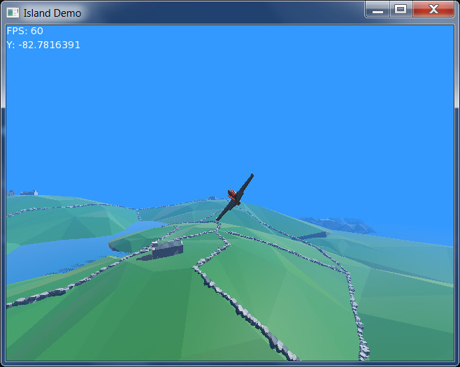
This is a very basic demo that uses physics to create a simple arcade-oriented plane you can fly around an island. It uses two CC0-licensed models from Google Poly and looks something like this:
Download the code and media below before continuing, and open up island.monkey2 in the default Monkey2 editor, Ted2Go:
IslandDemo source and media [4.6 MB; note that this is NOT a secure server, but the zip file contains only source code — text — and the 3D media. Run it through your virus scanner for peace of mind!]
The controls are the cursor keys, plus A and Z for throttle. You can fly around the island and bounce off it, nothing more involved than that.
Note that the demo doesn’t implement proper flight dynamics, so you can’t stall, and basically will fly in a straight line, with minimal impact from gravity, unless actively controlling it. You can even fly backwards if you slow down enough! While it won’t make flight simulator fans happy, it is almost enough to create a Pilotwings-style arcade game. With some effort, simple stall behaviour could no doubt be implemented.
The intention of this post is that you scroll through the code at the same time, in order to see what each section is doing.
Importing modules
The code starts by importing a few standard monkey2 modules: std, mojo, mojo3d, and mojo3d-loaders (the latter to allow loading of the unaltered GLTF-format 3D models straight from Google Poly). It then declares that we are ‘using’ them, in order to avoid typing full paths to functions, etc. (So instead of mojo3d.Model, for instance, we can just type Model.)
#Import "<std>"
#Import "<mojo>"
#Import "<mojo3d>"
#Import "<mojo3d-loaders>"

#Import "aerialcamera"
#Import "assets/"

Using std..
Using mojo..
Using mojo3d..
#Import “aerialcamera” here refers to a single external .monkey2 file, importing the AerialCamera class defined there — this has been separated out as it’s rather complex and made the code appear too cluttered, and isn’t relevant to the core point of this post. (It’s also rather hacky.)
The IslandDemo class
Next comes the main IslandDemo class, which implements the core application. In Monkey2, mojo3d applications extend the Window class and define the various built-in methods required by the Window class.
Note that the program starts in the Main function, which has been moved to the end of the code in this case, as it’s pretty uninteresting, simply setting up the core application and calling IslandDemo.New, followed by App.Run to begin.
We start out with a few constants and necessary fields:
Class IslandDemo Extends Window

' Set this to False if it runs slowly on low-end devices!

Const GROUND_SHADOWS:Bool        = True

Const WINDOW_WIDTH:Int            = 640
Const WINDOW_HEIGHT:Int            = 480
Const WINDOW_FLAGS:WindowFlags    = WindowFlags.Resizable

'    Const WINDOW_WIDTH:Int            = 1920
'    Const WINDOW_HEIGHT:Int            = 1080
'    Const WINDOW_FLAGS:WindowFlags    = WindowFlags.Fullscreen

Field scene:Scene
Field camera:AerialCamera
Field plane:PlaneBehaviour

...
If you find the application runs slowly on a low-end device, such as a typical laptop, try changing GROUND_SHADOWS to False — the extensive self-shadowing can cause performance problems on such devices.
You can comment-out the existing window width/height/flags values and uncomment those below to create a full-screen 1080p display.
We also define a few fields for the mojo3d scene, our aerial camera and a set of physics behaviours for the plane.
The New method simply sets up the application’s window.
Scene setup
Next up is the OnCreateWindow method, which is where media gets loaded and everything is set up ready for the game to start. We start with the 3D scene:
	Method OnCreateWindow () Override

		' ---------------------------------------------------------------------
		' Scene setup:
		' ---------------------------------------------------------------------
		' Gets a reference to the mojo3d default scene and sets a few options...
		' ---------------------------------------------------------------------

		scene									= Scene.GetCurrent ()

			scene.ClearColor					= New Color (0.2, 0.6, 1.0)
			scene.AmbientLight					= scene.ClearColor * 0.25
			scene.FogColor						= scene.ClearColor
			scene.FogNear						= 128
			scene.FogFar						= 2048

...
Here we set up the basic scene parameters, obtaining a handle to the default scene for ease of reference, then setting up the background colour, ambient light colour, fog colour and where the fog starts and ends relative to the camera.
The camera
Next up is setting up a handle to an aerial camera, which simply follows the plane around the scene. AerialCamera is a class defined in aerialcamera.monkey2 and just makes for a more interesting view of the scene than attaching a fixed camera. Its implementation isn’t relevant here, and frankly even I don’t fully understand how it works… and I wrote it! (Good old trial and error.)
The Sun
Then we set up a simple light, tell it to cast shadows in the scene (this will then affect any entity whose CastsShadow property is True). It’s angled to always cast a diagonal light upon the scene.
The default light type is ‘directional’, which means that it casts a universal wall of light across everything in the scene, regardless of where it’s positioned. Just think of it as the Sun!
		' ---------------------------------------------------------------------
		' Light setup:
		' ---------------------------------------------------------------------
		' Creates a light representing the Sun. The default light type is directional,
		' a universal 'wall' of light pointing in a given direction...
		' ---------------------------------------------------------------------

		Local light:Light						= New Light

			light.CastsShadow					= True

			light.Rotate (45, 45, 0)

...
The ground
Following this is the ground setup:
		' ---------------------------------------------------------------------
		' Ground model and physics setup:
		' ---------------------------------------------------------------------
		' Loads an external model and adds a physics collider and rigid body...
		' ---------------------------------------------------------------------

		Local ground_size:Float					= 4096 * 0.5
		Local ground_box:Boxf					= New Boxf (-ground_size, -ground_size * 0.5, -ground_size, ground_size, 0, ground_size)
		Local ground_model:Model				= Model.Load ("asset::model_gltf_6G3x4Sgg6iX_7QCCWe9sgpb\model.gltf")'CreateBox( groundBox,1,1,1,groundMaterial )

			ground_model.CastsShadow			= GROUND_SHADOWS

			ground_model.Mesh.FitVertices (ground_box, False)

			For Local mat:Material = Eachin ground_model.Materials
				mat.CullMode = CullMode.Back
			Next

		Local ground_collider:MeshCollider		= ground_model.AddComponent <MeshCollider> ()

			ground_collider.Mesh				= ground_model.Mesh

		Local ground_body:RigidBody				= ground_model.AddComponent <RigidBody> ()

			ground_body.Mass					= 0

...
Breaking this down, we are loading a model, located within a sub-folder of the assets folder and scaling it to fit within a given volume:
		Local ground_size:Float					= 4096 * 0.5
		Local ground_box:Boxf					= New Boxf (-ground_size, -ground_size * 0.5, -ground_size, ground_size, 0, ground_size)
		Local ground_model:Model				= Model.Load ("asset::model_gltf_6G3x4Sgg6iX_7QCCWe9sgpb\model.gltf")'CreateBox( groundBox,1,1,1,groundMaterial )

			ground_model.CastsShadow			= GROUND_SHADOWS

			ground_model.Mesh.FitVertices (ground_box, False)

			For Local mat:Material = Eachin ground_model.Materials
				mat.CullMode = CullMode.Back
			Next

...
The size of the ground, 4096 metres by 4096 metres, was decided by simply reloading and trying different values until the buildings looked ‘about right’ relative to the plane. (The ground model by default appears very small within the scene.)
A Boxf object (a set of bounds defining a box, using floating-point values) defines the area it will fit within. The size is halved when it’s defined, as we scale in each direction, therefore half to the left, half to the right, and so on.
Model.Load is used to load the .gltf-format model (note that this will only work if mojo3d-loaders is imported). The “asset::” prefix refers to the assets folder.
Then we set up shadows according to the True/False status of the GROUND_SHADOWS constant defined earlier and fit the vertices (3D points) of the model’s Mesh (the raw 3D data) to our box.
The False parameter of FitVertices allows us to override the default aspect ratios of the mesh.
We then iterate through the model’s materials — groupings of colours and/or textures — and enable backface-culling. (From memory, the model had front- and back-facing triangles — or perhaps it was just the plane, and I applied it to both!)
The ground’s physics
Next, we set up the ground’s physics:
		Local ground_collider:MeshCollider		= ground_model.AddComponent <MeshCollider> ()

			ground_collider.Mesh				= ground_model.Mesh

		Local ground_body:RigidBody				= ground_model.AddComponent <RigidBody> ()

			ground_body.Mass					= 0

...
Important: To enable physics on an entity, we need a collider, which defines the shape used for collision detection, and a rigid body, which defines the parameters used to physically control the entity.
In this case, the type of collider is MeshCollider, which uses the raw triangles of the underlying mesh. This can be slow and should be avoided where possible in favour of rougher approximations, such as spheres and cylinders. However, with a terrain like this, nothing else will do.
Because they are so ‘expensive’, mesh colliders will only work for static objects in the scene.
We point the mesh collider’s Mesh field to the model’s own mesh, from which it will be automatically set up.
We also set up the ground’s rigid body, which holds its motion and collision response parameters. In this case, all we need is to set the mass to zero — this means that the object will be fixed in place, its position unaffected by gravity, collisions, etc.
Note that both the collider and the rigid body are ‘added’ to the entity (the ground model) as ‘components’ — like bolting on physics responses to a model that would otherwise have to be manually-controlled and would simply pass through other models.
The plane
Next up, the plane itself!
		Local plane_size:Float					= 16.83 * 0.5
		Local plane_box:Boxf					= New Boxf (-plane_size, -plane_size, -plane_size, plane_size, plane_size, plane_size)

		Local plane_model:Model					= Model.Load ("asset::1397 Jet_gltf_3B3Pa6BHXn1_fKZwaiJPXpf\1397 Jet.gltf")

			plane_model.Mesh.FitVertices (plane_box)
			plane_model.Mesh.Rotate (0, 180, 0)

			plane_model.Move (0.0, 5.0, 0.0)

		' Cull hidden tris...

		For Local mat:Material = Eachin plane_model.Materials
			mat.CullMode = CullMode.Back
		Next

...
Again, we create a box within the plane will be fitted. In this case, I’ve used the wingspan of a real-world plane (the SEPECAT Jaguar) to define the widest point of the box, and (unlike the ground box) have left out the last parameter to FitVertices, which is True by default, in order to retain the model’s aspect ratios automatically. (This means it won’t look ‘squished’ in any direction, even if I don’t know the correct values for each.)
We load the plane and scale to fit within its box.
However! This model faces towards the camera when loaded, so the plane would be flying backwards. For reasons too complex to go into, simply rotating the model (the collection of 3D mesh, texture and other data) won’t work with the rigid body — the plane initially flew backwards.
Near the end of the source code is a class extension (“Class Mesh Extension”) that implements a way to rotate the raw 3D mesh while retaining the orientation of the model. Hopefully something of this nature will be added to mojo3d in the future!
The model is then positioned at its starting point. In this case, it was probably unnecessary to do so, the code to move upwards by 5 units left in place in error, but it’s important to note that you need to position a model correctly prior to adding any physics colliders or rigid bodies. You can’t manually re-position them after creation without causing problems with the physics processing.
Again, backface culling is enabled throughout the model’s materials. (If you’re creating your own models, you can avoid creating front-and-back triangles in your modeller, and avoid this step, but for models created by others you can’t control this, other than manually-editing the model yourself.)
The plane’s physics
Similar to the ground’s physics setup, we create a collider and a rigid body:
		' Physics setup...

		Local plane_collider:SphereCollider		= plane_model.AddComponent <SphereCollider> ()

			plane_collider.Radius				= plane_size * 0.6

		Local plane_body:RigidBody				= plane_model.AddComponent <RigidBody> ()

			plane_body.Mass						= 10954.0
			plane_body.Restitution				= 0.5
			plane_body.AngularDamping			= 0.9
			plane_body.LinearDamping			= 0.5
			plane_body.Friction					= 0.0

...
In this case, the collider is a SphereCollider, and we set its Radius parameter according to what we need. (This is simply the radius at which it will collide with other physics objects.)
The plane’s body is more interesting, as this time it’s not a static body with mass of 0, but intended to be fully dynamic and affected by physical forces and collisions.
The mass here is set to the real-world mass of the Jaguar, measured in kilograms. This isn’t strictly necessary: originally the plane flew with a default mass of 1 kg and controlled in exactly the same way, with the forces that are later applied being scaled down 10,000 times!
It’s more important that dynamic bodies in the scene have correct relative values so that they appear to bounce off each other correctly.
A few other properties are defined:
- Restitution: This simply defines how bouncy an object is, in a range typically from 0 to 1. A value of 1 will bounce away from another object at exactly the same velocity it hit with; a value of 0.5 will bounce away with half the velocity, etc. Note that if the other body’s restitution is another value, that will also affect the bounce response.
- AngularDamping: By default, with a value of zero, any rotation forces applied (known as torque) will leave the object rotating forever, until counteracted with a torque in the opposite direction. By setting AngularDamping to higher values (up to 1), you can have the object’s rotation reduce automatically. The plane is very hard to control without damping — try setting it to zero, and some other values in-between!
- LinearDamping: This works in similar fashion to AngularDamping, but on forces operating directionally (pushing and pulling forces). With LinearDamping set to zero, the object continues in a given direction until counteracted; higher values cause the object to slow down gradually. If you set this to zero, you’ll find that when you turn the plane around, it continues flying in the direction it was travelling (ie. backwards!).
- Friction: This is used to decide how the object is slowed by grazing another object. It’s set to zero here so that when colliding with the ground, the underlying sphere doesn’t rotate as a result of the collision, as a real-world ball would. Try setting this to 0.5 and clipping the ground — the plane will tumble end-over-end. (More realistic, but less fun while simply flying around.)
Try playing around with all of these values — you can always set them back to those shown above to regain the original behaviour.
(You may also want to play with the pitch_rate, roll_rate and throttle parameters defined in PlaneBehaviour, as these can counteract the effects of changing the above values.)
The plane’s physics behaviour and collision visualisation
Next, we set up the plane model’s physics behaviour — defined in the PlaneBehaviour class — which gives us a way to modify the plane’s movement and physics responses on each frame, and create a simple model for visualisation of the physics sphere collider, by parenting a semi-transparent sphere model, of the same radius as the sphere collider, to the plane model. This is disabled by default — try setting the coll_vis variable to True and running the program. You can tweak plane_collider.Radius (defined earlier) to see how it looks and responds with different radii.
Finally, we hide the mouse pointer from view.
		plane									= New PlaneBehaviour (plane_model)

		' Debug sphere for visibility of collision radius only...

		Local coll_vis:Bool = False

		If coll_vis

			' Create a sphere model used to represent the collision sphere; hidden by default...

			Local plane_collider_vis:Model					= Model.CreateSphere (plane_collider.Radius, 16, 16, New PbrMaterial (Color.White), plane_model)

				plane_collider_vis.Alpha					= 0.25

		End

		' Hide mouse pointer...

		Mouse.PointerVisible					= False

...
PlaneBehaviour is where the plane’s controls are defined. More on Behaviours in the next post!
Happy flying!